Air Conditioning System Operation
GENERAL INFORMATION.
Compressor
The compressor is driven by a belt from the engine crankshaft through a disengageable drive. An electromagnetic clutch is built into the compressor pulley. When the clutch is disengaged, the compressor shaft does not rotate. When the clutch is engaged, current flows through the electromagnet coil and the electromagnetic force presses the clutch driven plate against the rotating pulley. The compressor shaft begins to rotate together with the
pulley.
During operation, the compressor compresses refrigerant vapor, which is supplied to it through the
line from the evaporator. At the compressor outlet, the vapor pressure and temperature
increase. Refrigerant oil, which lubricates the friction surfaces of the compressor, is supplied to it
mixed with the refrigerant vapor.
Pressure Relief Valve
The compressor is equipped with a pressure relief valve, which performs a protective function. In some cases, the compressor outlet pressure may reach the maximum permissible value.
To prevent damage to the system, the pressure relief valve is set to a cut-off pressure of 3140-3623 kPa when R-12 refrigerant is used and 3171-4137 kPa when R-134a refrigerant is used. If
the pressure relief valve has operated, eliminate the causes of excessive pressure increase (high-pressure switch failure, electric fan failure, etc.)
and, if necessary, replace the refrigerant and refrigerant oil.
Condenser
The condenser is located in front of the engine cooling system radiator and is designed for rapid cooling and condensation of the
refrigerant vapor compressed by the compressor
into high-pressure liquid. Cooling is provided by
heat transfer to the air flowing over the finned tube coil of the heat exchanger.
Orifice Tube
The plastic orifice tube with a metering orifice and mesh filter is installed in the line supplying liquid refrigerant to the evaporator. The orifice restricts the flow of liquid refrigerant and reduces pressure
at the evaporator inlet. The orifice tube and orifice are protected from clogging by mesh filters located at the inlet and outlet of the tube. The orifice tube is replaced only as an assembly. After the engine is stopped (with the A/C system on), liquid refrigerant continues to flow for some time (until
pressures equalize) through the orifice tube from the high-pressure zone to the low-pressure zone. This flow is accompanied by a characteristic hissing sound, which can be heard for 30-60 s after the engine is stopped. This is normal.
Evaporator
The evaporator is designed to cool and reduce the humidity of air
entering the passenger compartment. After the liquid refrigerant passes
through the orifice tube, the pressure drops and the refrigerant enters the evaporator core. Cooling of the air flowing over the finned evaporator surface
is provided by heat transfer from the air to the refrigerant, which changes into
a gaseous state with heat absorption. When the air is cooled on the cold evaporator tubes and fins, water vapor contained in the air condenses at the same time. When the A/C is on, the condensed moisture drains from the evaporator.
Receiver-Drier
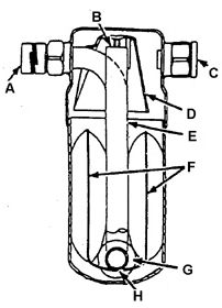
Receiver-drier design: A. OUTLET FITTING
B. INLET OPENING OF PICKUP TUBE
C. INLET FITTING
D. BAFFLE
E. PICKUP TUBE
F. DESICCANT CARTRIDGE
G. FILTER
H. LOCATION OF OIL RETURN HOLE IN PICKUP TUBE
The sealed receiver-drier is connected to the evaporator outlet line. Gaseous refrigerant with a small amount of liquid refrigerant and drops of refrigerant oil enters the receiver-drier.
A desiccant cartridge is located in the lower part of the receiver-drier.
It protects the system from moisture. A small hole is made in the lower
part of the pickup tube for mixing refrigerant vapor
with refrigerant oil and ensuring oil circulation in the system. Fittings for connecting the lines are located in the upper part of the receiver-drier body.
A similar fitting can be used to install the compressor unloading switch. The switch can be replaced without discharging the A/C system.
The receiver-drier is not repairable and is replaced only as an assembly.
Heater Core
The heater core is designed to raise the temperature of air entering
the passenger compartment. Ambient air is heated by heat from
the engine coolant circulating through the tubes of the heater core. Intensive heat exchange between the hot coolant and the cold air is provided by
the extended external surface of the finned tubes.
Test yourself
A quick Daewoo Nexia quiz: every answer comes with an explanation and a link to the manual page.