General Description
GENERAL INFORMATION
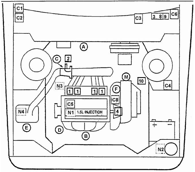
Layout of main components of the 1.5-liter (SOHC) engine systems with MPI
ECU WIRING, FUSES AND CONNECTORS.
C
1. ECU.
C
2. DIAGNOSTIC CONNECTOR.
3. "ENGINE SERVICE REQUIRED" LAMP (ESL).
C
5. ECU "GROUND" WIRE (MASS).
C
6. FUSE/RELAY PANEL.
C
8. FUEL PUMP CHECK CONNECTOR.
COMPONENTS OPERATING INDEPENDENTLY OF THE ECU.
N
1. POSITIVE CRANKCASE VENTILATION (PCV) SYSTEM.
N
2. EVAPORATIVE CANISTER (LOCATED UNDER THE SPLASH SHIELD).
N
3. OIL PRESSURE SWITCH (LOCATED IN THE CYLINDER BLOCK UNDER THE INTAKE MANIFOLD).
N
4. AIR CLEANER.
COMPONENTS OPERATING IN CONJUNCTION WITH THE ECU.
1. FUEL INJECTORS.
2. IDLE AIR CONTROL VALVE.
3. FUEL PUMP RELAY.
4. DISTRIBUTOR WITH IGNITION TIMING CONTROL SYSTEM.
8. COOLING FAN RELAY.
9. AIR CONDITIONING COMPRESSOR RELAY.
10. IGNITION COIL/SENSOR.
A. MANIFOLD ABSOLUTE PRESSURE (MAP) SENSOR.
B. EXHAUST GAS OXYGEN (HEGO) SENSOR.
C. THROTTLE POSITION SENSOR (TPS).
D. ENGINE COOLANT TEMPERATURE (ECT) SENSOR.
E. INTAKE AIR TEMPERATURE (IAT) SENSOR.
F. VEHICLE SPEED SENSOR (VSS).
M. PARK/NEUTRAL POSITION (PNP) SWITCH.

Fuel System
1. FUEL TANK CAP.
2. BOLT.
3. FUEL FILLER NECK GASKET.
4. FUEL FILLER PIPE.
5. FUEL FILLER PIPE CLAMP.
6. BOLT.
7. CLAMP.
8. WORM CLAMP.
9. VENT PIPE RETAINER.
10. VENT PIPE.
11. WASHER.
12. NUT.
13. FUEL TANK MOUNTING STRAP.
14. STUD.
15. VENT PIPE.
16. PIPE RETAINERS.
17. CLAMP.
18. VENT HOSE.
19. EVAPORATIVE CANISTER.
20. NUT.
21. WASHER.
22. CANISTER STRAP.
23. CANISTER BRACKET.
24. FUEL LINE CLIPS.
25. RUBBER BUSHING.
26. FUEL SUPPLY LINE.
27. FUEL RETURN LINE.
28. Bolt.
29. WASHER.
30. FUEL FILTER.
31. CLAMP.
32. FILTER BRACKET.
33. HOSE CLAMP.
34. FUEL SUPPLY HOSE.
35. FUEL RETURN HOSE.
36. FUEL LINE.
37. RUBBER BUSHINGS.
38. CLAMP.
39. HOSE CLAMP.
40. FUEL PUMP HOSE.
41. HOSE CLAMP.
42. REAR FUEL RETURN HOSE.
43. FUEL TANK.
44. FUEL PUMP STRAINER.
45. FUEL PUMP.
46. FUEL PUMP GASKET.
47. FUEL LEVEL SENSOR.
48. FUEL LEVEL SENSOR GASKET.
The engine is designed to run only on unleaded gasoline. Unleaded fuel ensures normal operation of the system.
neutralizes toxic components of the exhaust gases, reduces deposits on spark plugs and extends the service life of the engine oil. When performing
maintenance or repair of the fuel system, observe the following
rules.
Always disconnect the negative battery cable, except
when voltage is required to test fuel system components.
Before disconnecting fuel lines or other components, relieve the fuel system pressure to atmospheric pressure.
When installing and removing line fittings, always use two wrenches: one to tighten the nut and the other to hold the fitting. Torque for threaded connections is
30 N·m.
The fuel injection system uses lines and fittings with
O-rings.
In the multi-point fuel injection system, the injectors are installed in the intake manifold at each engine cylinder.
The fuel injectors are controlled by the engine ECU, which
supplies the required amount of fuel in all engine operating
modes.
The electric fuel pump is located in the fuel tank.
The pump maintains constant circulation of cool fuel through the supply and return
lines.
A relay is used to activate the fuel pump. When the ignition key is turned to the
RUN position, the relay energizes the pump for 1.5 – 2.0 s to supply fuel to the injectors. If the engine ECU does not receive a signal from the ignition distributor during this time, the ECU turns off the relay and the fuel pump. When the ECU receives a signal from the distributor, the relay energizes the pump again.
The fuel tank is normally located underneath the rear of the vehicle.
To prevent gasoline vapor from escaping into the atmosphere, the tank is equipped with a vent line connected to the evaporative emission canister.
Before performing any work on the fuel system, do the following. 1) Disconnect the negative battery cable.
2) Wear safety glasses.
3) Drain the fuel with a pump or siphon into a container approved for
fuel storage.
To prevent accidental refueling with leaded gasoline, the filler neck is fitted with a restrictor for the nozzle diameter
and a deflector.
The fuel level sensor is installed at the front of the fuel tank bottom. Fuel is supplied by the pump through a line located at the top of the fuel tank,
and returns to the tank through the lower hose.
Test yourself
A quick Daewoo Nexia quiz: every answer comes with an explanation and a link to the manual page.