Shift Lock System - General Information, Inspection, Replacement and Adjustment of Control Solenoid
The vehicles covered in this Manual are equipped with a Supplemental Restraint System (SRS). Before performing any work near the airbag module, steering column, or instrument panel, disable the SRS to prevent injury from accidental deployment (see Section Body Electrical System). SRS wiring can be easily identified by its yellow insulation.
General Information
All AT-equipped models are fitted with a shift lock system that prevents unintentional gear shifting. The shift lock system consists of two subsystems: the shift lock system and the key interlock system.
Key Interlock System
The system prevents the key from being removed from the ignition switch until the selector lever is moved to the "P" position. When the key is inserted into the ignition switch with the lever in any position other than "P", the electromagnetic actuator is energized, making key removal impossible. To remove the key, move the lever to the "P" position.
Shift Lock System
The system prevents the selector lever from being moved from "P" to "R" or "D" without depressing the brake pedal. The lock also engages when the brake and accelerator pedals are depressed at the same time. If the system fails, the lever can be released by inserting the key into the special slot near the lever assembly.
INSPECTION
PROCEDURE
1. The following checks of the electromagnetic actuators of both locks can be performed by a home mechanic. More detailed system diagnosis must be performed at an authorized service workshop.
Ignition Key Lock Electromagnetic Actuator
2. Remove the lower instrument panel trim and knee bolster (see Chapter Body).
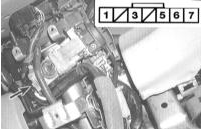
3. Disconnect the 7-pin connector of the main wiring harness.
4. Check continuity between the connector terminals in the various ignition switch positions. When the key is pressed into the lock, there must be continuity between terminals 5 and 7; when the key is released, there must be none.
5. Make sure the key cannot be removed when battery voltage is applied to terminals 7 (+) and 3 (-).
6. If the key is removed, the lock system is functioning correctly. Otherwise, replace the ignition switch assembly (see Chapter Body Electrical System). Lock components are not sold separately.
Shift Lock Electromagnetic Actuator
7. Remove the console (see Chapter Body).

8. Disconnect the 2-pin connector of the shift lock electromagnetic actuator.
9. Using two jumper wires, briefly connect the battery to the connector terminals (positive to terminal 1, negative to terminal 2). With power applied, the lever must not be movable; otherwise, replace the actuator.
Reversing the battery polarity may damage the diode inside the electromagnetic assembly.
10. Remove the jumper wires and move the selector lever back to the "P" position.
11. Make sure the lever lock releases when it is pressed down and re-engages when released.
Selector Lever Position Switch Sensor
12. Remove the center console (see Chapter Body Electrical System).
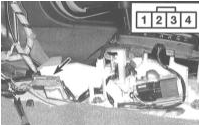
13. Disconnect the 4-pin connector of the selector lever position switch sensor in the center console area.
14. Move the lever to "P" and check for continuity between terminals 3 and 4 of the connector.
15. Now move the lever to "N"; continuity between terminals 3 and 4 must disappear.
16. If the test results are negative, replace the position switch sensor.
Replacement and Adjustment of Electromagnetic Actuator
PROCEDURE
The procedure described below applies only to the shift lock actuator. Information on replacing the ignition key lock electromagnetic actuator is given in the section on replacing the ignition lock cylinder (see Chapter Body Electrical System).
1. Remove the center console (see Chapter Body).
2. Disconnect the 2-pin wiring connector of the electromagnetic actuator.
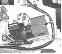
3. Using a pry tool, remove the actuator retainer.
4. Remove the actuator assembly with the plunger and plunger spring.
5. Installation is the reverse of removal.
Test yourself
A quick Honda Accord quiz: every answer comes with an explanation and a link to the manual page.