Engine Control System/Fuel System
ETC (Electronic Throttle Control) System
In this manual: Engine Control System/Fuel System
18steps
~108min
4/5difficulty
Done 0 of 18
Description and Operation
Description
The Electronic Throttle Control (ETC) system consists of a throttle body with a built-in control motor and a throttle position sensor (TPS). Unlike the conventional mechanical throttle system, which controls the throttle valve by a cable connected to the accelerator pedal, the ETC system controls the opening and closing of the throttle valve by the ECM through the ETC motor, based on the APS (Accelerator Position Sensor) signal connected to the electronic accelerator pedal module. The TPS signal is used to provide throttle position feedback to the ECM. In addition, the ETC system has the advantage of implementing the cruise control function without additional external cruise control modules/cables.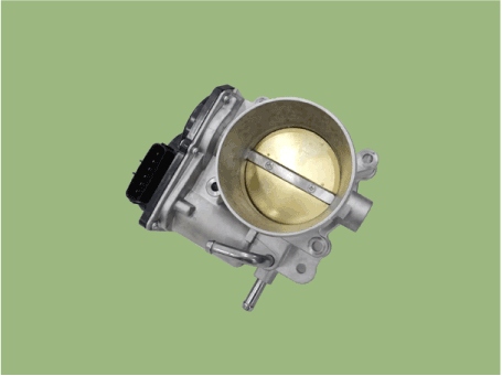
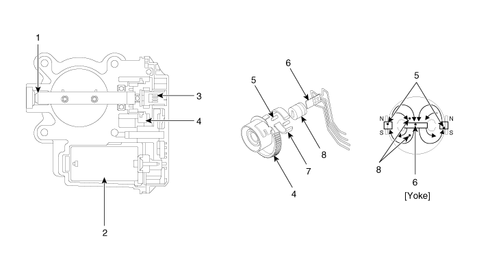
| 1. Dry Bearing 2. DC Motor 3. Non-contact Hall Sensor 4. Gear |
5. Magnet 6. Hall IC 7. Clamp 8. Stator |
Specifications
Specification
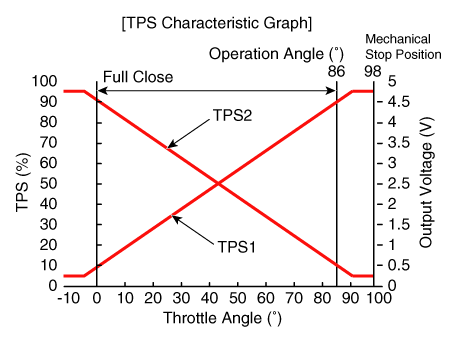
[Throttle Position Sensor (TPS)]| Throttle Angle (°) | Output Voltage (V) [Vref = 5 V] | |
| TP1 | TP2 | |
| 0 | 0,5 | 4,5 |
| 10 | 0,96 | 4.05 |
| 20 | 1,41 | 3,59 |
| 30 | 1,87 | 3.14 |
| 40 | 2,32 | 2,68 |
| 50 | 2,78 | 2,23 |
| 60 | 3,23 | 1,77 |
| 70 | 3,69 | 1,32 |
| 80 | 4.14 | 0,86 |
| 90 | 4,60 | 0,41 |
| 98 | 4,65 | 0,35 |
| THA (0) | 0,5 | 4,5 |
| THW (86) | 4.41 | 0,59 |
| Item | Specification |
| Coil Resistance (Ω) | 0,3–100 [20 °C] |
Troubleshooting
Fail-Safe Mode
| Item | Fail-safe | |
| ETC Motor | Throttle Stuck at 7° | |
| TPS | TPS 1 Fault | ECM Reads TPS2 |
| APS 2 Fault | ECM Reads TPS1 | |
| TPS 1, 2 malfunction | Throttle Stuck at 7° | |
| APS | APS 1 Malfunction | ECM Reads APS 2 |
| APS 2 Malfunction | ECM Reads APS 1 | |
| APS 1, 2 malfunction | Engine Idle Condition | |
|

Circuit Diagrams
Schematic Diagram
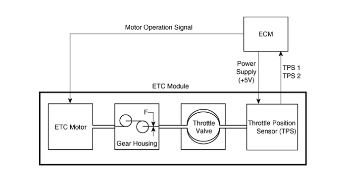
Wiring Diagram
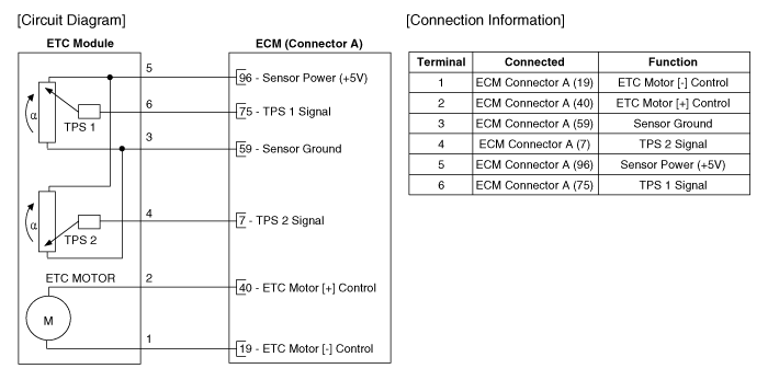
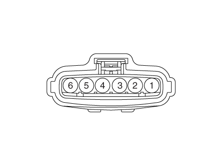
Repair Procedures
Inspection
If the idle speed is unstable or the engine stalls, check the operation of the ETC module using the diagnostic tool. If necessary, remove carbon deposits from the throttle body.- Connect the diagnostic tool to the Data Link Connector (DLC).
- Select "Vehicle Software Management" → "Inspection/Test" → "ETC Performance Test" in the diagnostic tool menu.
- Perform the "ETC Module Inspection" procedure as instructed by the message.
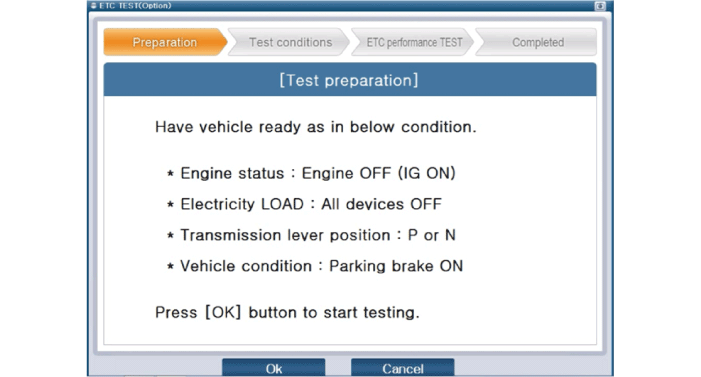
- If the ETC module or TPS signal check result is NG, perform the ETC module cleaning procedure.
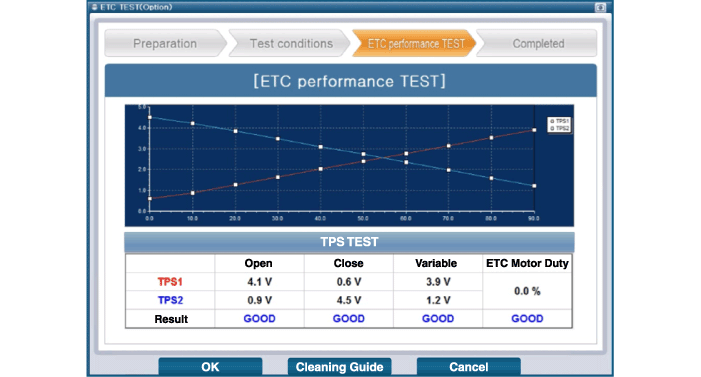
Removal
- Turn the ignition switch OFF and disconnect the negative (-) battery terminal.
- Remove the air cleaner assembly. (Refer to Engine Mechanical System - "Air Cleaner")
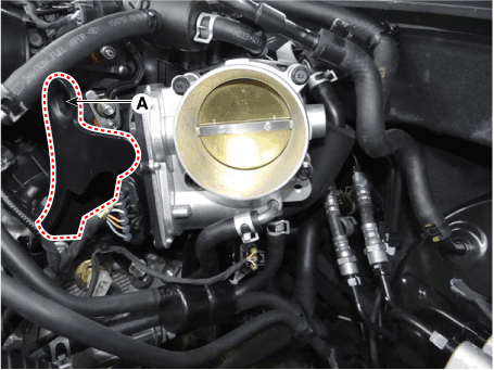
- Remove the engine mount (A) after loosening the mounting bolt.
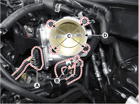
- Disconnect the ETC module connector (A).
- Disconnect the coolant hoses (B).
- Remove the ETC module (D) after loosening the mounting bolts (C). ETC throttle body mounting bolt: 14.7 - 24 N·m
Cleaning
- Remove the ETC module. (Refer to Engine Control System - "ETC System")
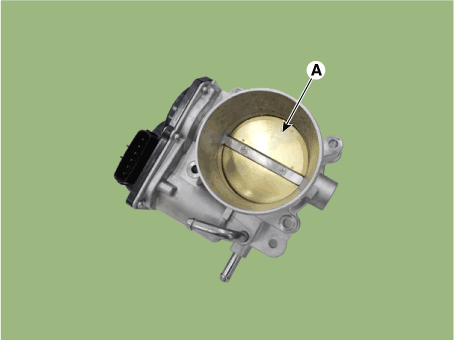
- Hold the ETC module panel (A) open.
- Remove contamination from the throttle body using a soft cloth moistened with cleaning solution.
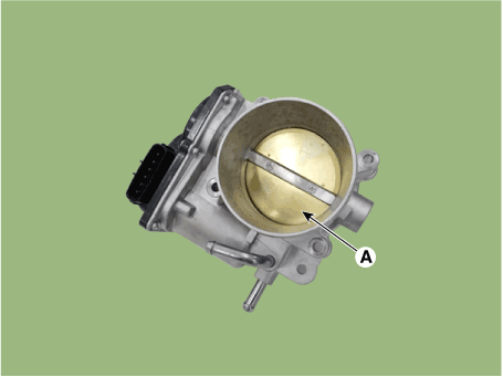

- Do not spray cleaning solution directly onto the ETC. Use a lint-free cloth moistened with cleaning solution.
- Be careful not to wash away the coating fluid around the shaft. If the coating fluid is removed, idle control failure may occur due to foreign matter entry or excessive air leakage.
- After cleaning, reinstall the ETC module, then perform the ETC module learning procedure. (Refer to Engine Control System - "ETC System" - Adjustment)
Installation
|

|

|

|

- Install in the reverse order of removal.
Adjustment
ETC Module Learning Procedure: When replacing or reinstalling the ETC module, be sure to perform the ETC module learning procedure.- Wait 1 minute with the ignition switched ON.
- Start the engine and maintain idle speed for 15 minutes.
- Wait for 1 minute with the ignition switched off.
- Restart the engine and check that the idle speed is stable.

- Failure to perform the ETC module learning procedure after replacement or reinstallation may cause the MIL to illuminate with diagnostic trouble codes.
Test yourself
A quick Hyundai Palisade quiz: every answer comes with an explanation and a link to the manual page.
Was this page helpful?