Engine Control System/Fuel System
Repair Procedures - Injector
In this manual: Engine Control System/Fuel System
18steps
~113min
5/5difficulty
1special tools
Done 0 of 18
Inspection
- Turn the ignition off.
- Disconnect the injector connector.
- Measure the resistance between terminals 1 and 2 of the injector.
- Make sure the resistance is within specification.
Specification: Refer to "Specifications"
Removal
|

- Turn the ignition switch OFF and disconnect the negative (-) battery cable.
- Relieve the residual fuel pressure in the fuel line. (Refer to Fuel System - Repair Procedures - "Relieve Residual Fuel Pressure in Fuel Line").
When the fuel pump fuse is removed, a diagnostic trouble code (DTC) is stored. Clear the DTC with GDS after completing the "Relieve Residual Fuel Pressure in Fuel Line" procedure.
- Remove the delivery pipe and injector assembly. (Refer to Fuel System - "Delivery Pipe")
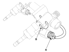
- Remove the connector (A) and retaining clip (B), then separate the injector from the delivery pipe.
Installation
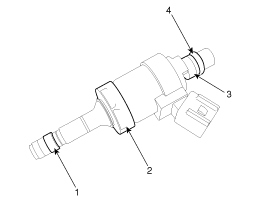
- Combustion Seal
- Rubber Washer
- Support Ring
- O-ring
|
|
|
|
|
|

|
- Install in the reverse order of removal.
Replacement
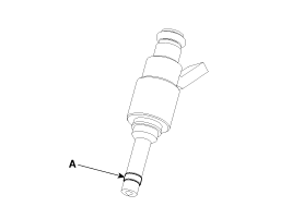
Replace the injector combustion seal with a new one to prevent leakage after the injector is removed.- Remove the combustion seal (A) using cutting pliers.

Carefully grasp the O-ring, pull it to form a small loop, then cut it. Be careful not to damage the valve sleeve surface with the cutting pliers. - Before installing the O-ring, clean the groove with a clean cloth. Any carbon deposits on the injector sealing surface must be thoroughly removed with a brass wire brush.

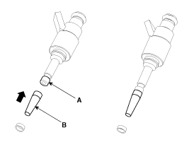
The surfaces of the new O-ring must be clean and free of grease. - Place the O-ring installation guide (B) (SST No.: 09353-2B000) on the injector tip to avoid damaging the injector tip (A). Push the O-ring (C) over the conical installation tool with your thumb and index finger until it enters the groove. The entire assembly should take no more than 2-3 seconds.

- To determine the O-ring size, first insert the injector into the calibration tool (A) (SST No.: 09353-2B000), then press and at the same time rotate it 180° in the calibration tool.
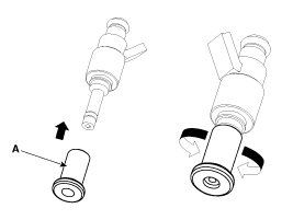
- Remove the injector from the gauge tool by turning it in the direction opposite to that used for pressing.
Make sure the O-ring is not damaged during assembly with the injector and that there are no scratches around its circumference. Do not reuse the combustion seal. The seal must be completely cleaned of grease and oil. - Check the installation of the combustion seal (A).
Test yourself
A quick Kia Cadenza VG Owner's Manual quiz: every answer comes with an explanation and a link to the manual page.
Was this page helpful?