AVN Antenna
Components and Component Location
Components
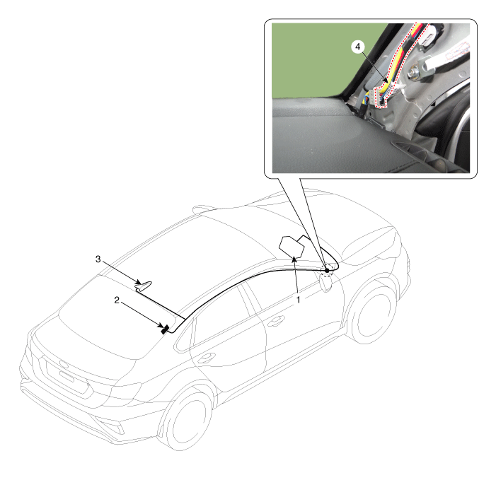
| 1. AVN Head Unit 2. Glass Antenna |
3. Roof Antenna 4. Antenna Power Cable |
Repair Procedures
Inspection
Glass Antenna
Glass Antenna Circuit Inspection
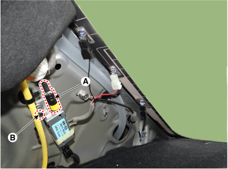
Remove the glass antenna and the rear pillar garnish (RH), then disconnect the power cable from the amplifier.
Turn on the radio.
Measure the voltage between terminal 2 of the antenna feeder cable harness (A) and body ground (B).
OK: Approximately 12 V (ACC+)
Antenna Grid Line Inspection
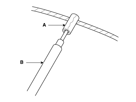
Wrap aluminum foil (A) around the tip of the tester probe (B), as shown in the illustration.
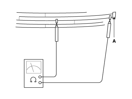
Touch one tester probe to the glass antenna terminal (A) and move the other tester probe along the antenna wires to check for continuity.
OK: Approximately 12 V (ACC+)
Glass Antenna Grid Line Repair
Lightly rub the area around the broken section (A) with fine steel wool, then wipe with alcohol.
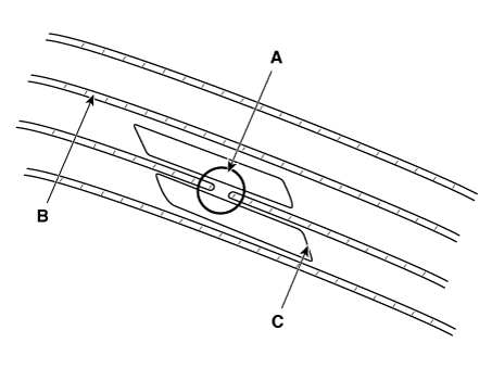
Carefully mask above and below the broken part of the glass antenna wire (B) with cellophane tape (C).
Using a small brush, apply a thick layer of conductive silver paint (A), extending approximately 1/8 in. on both sides of the break. Allow 30 minutes to dry.
Check the continuity of the repaired wire.
In the same way, apply a second layer of paint. Allow it to dry for three hours before removing the tape.
Antenna Cable
Check continuity between the center terminals of the antenna cable.
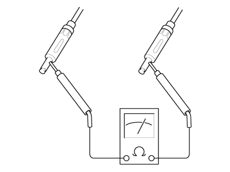
Check the continuity between the outer terminals of the antenna cable. There should be continuity.
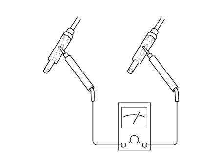
If there is no continuity, replace the antenna cable.
Check the continuity between the center pole (A) of the antenna cable and the glass antenna terminal (B). There must be continuity.
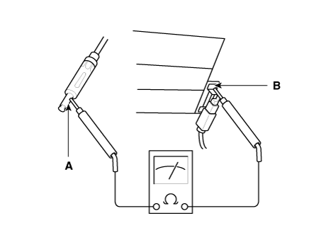
If there is no continuity, replace the antenna amplifier.
Check the continuity of the circuit between the center pole (A) and the outer pole (B) of the antenna cable. There should be no continuity.
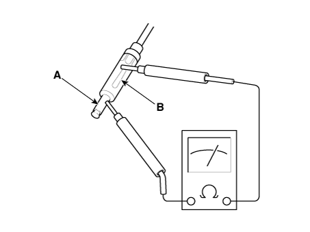
If there is continuity, replace the antenna cable.
Removal
Glass Antenna Amplifier
Remove the rear pillar garnish (RH).
(Refer to Body - "Rear Pillar Garnish")
Loosen the bolt, then remove the glass antenna amplifier (A) after disconnecting the connector.
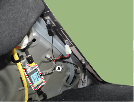
Roof Antenna
Disconnect the negative (-) battery terminal.
Remove the roof trim assembly.
(Refer to Body - "Roof Trim Assembly")
Disconnect the connector (A, B) from the antenna.
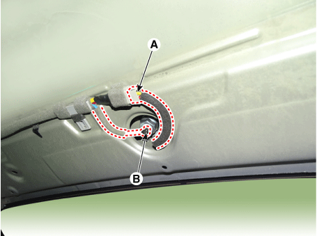
Remove the roof antenna (B) after loosening the nut (A).
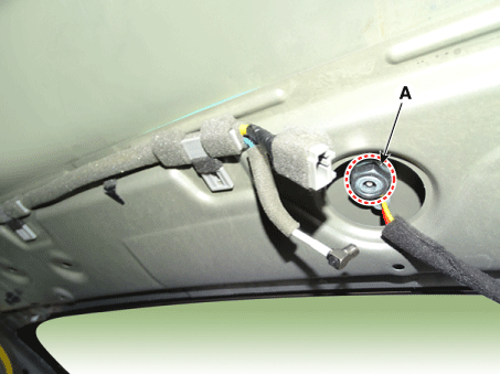
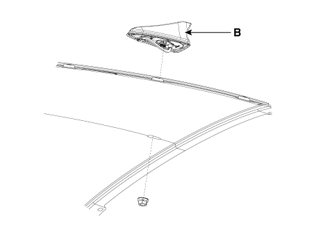
Wireless Antenna
Remove the instrument cluster.
(Refer to Indicators and Gauges - "Instrument Cluster")
Remove the wireless antenna (B) by loosening the screw after disconnecting the connector (A).
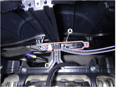
Installation
Install in the reverse order of removal.
Test yourself
A quick Kia Forte BD quiz: every answer comes with an explanation and a link to the manual page.