External amplifier
Components and Component Location
Component Location
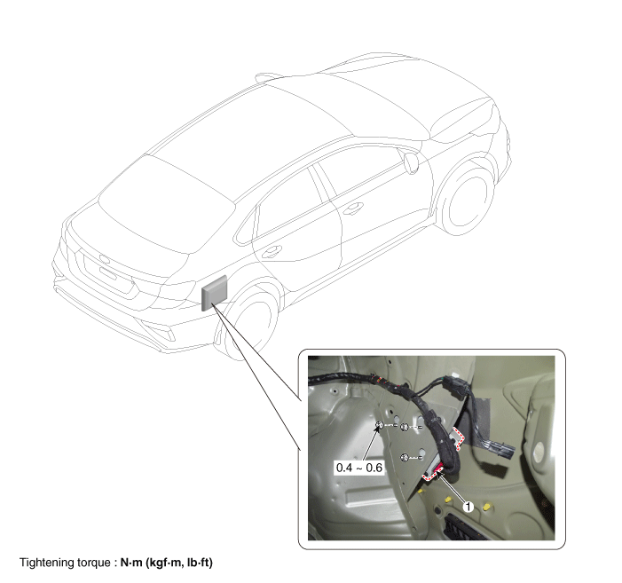
| 1. Amplifier assembly |
Circuit Diagrams
Connector and Terminal Function
[DRILL]
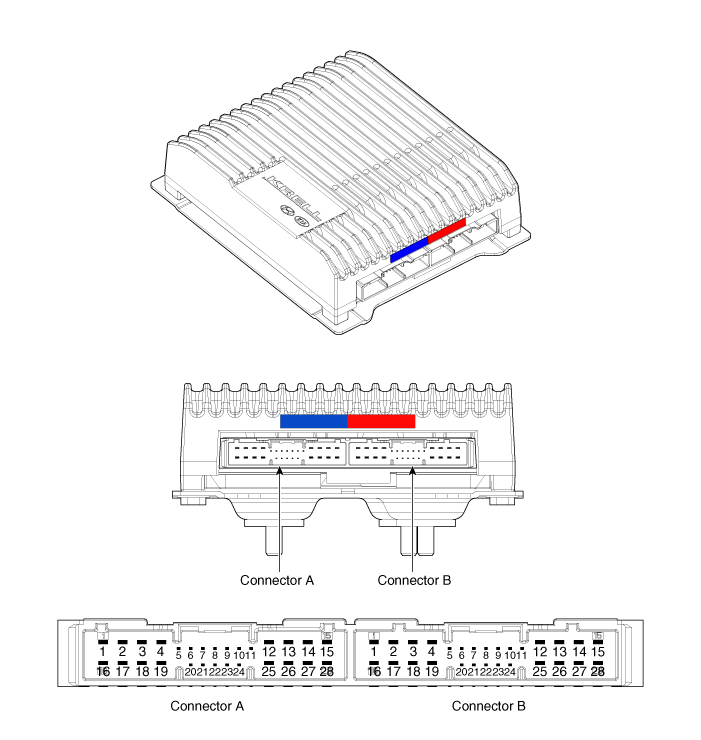
| No. | Connector A | Connector B |
| 1 | Battery (+) | Left rear door speaker (+) |
| 2 | Battery (+) | Left rear door speaker (-) |
| 3 | Battery (+) | Right rear door speaker (+) |
| 4 | Battery (+) | Right rear door speaker (-) |
| 5 | - | - |
| 6 | Multimedia CAN (High) | - |
| 7 | Multimedia CAN (Low) | - |
| 8 | ACC | - |
| 9 | Voice navigation amplifier (+) | - |
| 10 | - | - |
| 11 | - | - |
| 12 | Left front door speaker (+) | - |
| 13 | Left front door speaker (-) | - |
| 14 | Right front door speaker (+) | - |
| 15 | Right front door speaker (-) | - |
| 16 | Ground | Subwoofer speaker (+) |
| 17 | Ground | Subwoofer speaker (-) |
| 18 | Ground | Front center speaker (+) |
| 19 | Ground | Front Center Speaker (-) |
| 20 | Amplifier SPDIF (+) | - |
| 21 | Amplifier SPDIF (-) | - |
| 22 | Amplifier screen (ground) | - |
| 23 | Voice navigation amplifier (-) | - |
| 24 | IGN1 | - |
| 25 | Left front door tweeter (+) | - |
| 26 | Left front door tweeter (-) | - |
| 27 | Right front door tweeter (+) | - |
| 28 | Right front door tweeter (-) | - |
[Harman]
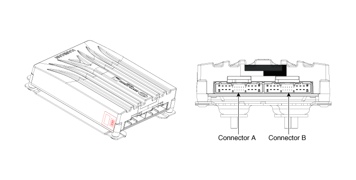
| No. | Connector A | Connector B |
| 1 | Battery (+) | Subwoofer 2 (+) |
| 2 | Battery (+) | Subwoofer 1 (+) |
| 3 | Battery (+) | Right front door tweeter (+) |
| 4 | Battery (+) | Left front door tweeter (+) |
| 5 | - | - |
| 6 | Multimedia CAN (High) | - |
| 7 | Multimedia CAN (Low) | - |
| 8 | ACC | - |
| 9 | Voice navigation amplifier (+) | - |
| 10 | - | - |
| 11 | - | - |
| 12 | - | Right rear door speaker (+) |
| 13 | - | Left rear door speaker (+) |
| 14 | - | Front center speaker (+) |
| 15 | - | - |
| 16 | Ground | Subwoofer 2 (-) |
| 17 | Ground | Subwoofer 1 (-) |
| 18 | Ground | Right front door tweeter (-) |
| 19 | Ground | Left front door tweeter (-) |
| 20 | SPDIF Amplifier (High) | - |
| 21 | Amplifier SPDIF (Low) | - |
| 22 | SPDIF Amplifier (Ground) | - |
| 23 | Voice navigation amplifier (-) | - |
| 24 | - | - |
| 25 | - | Right rear door speaker (-) |
| 26 | - | Left rear door speaker (-) |
| 27 | - | Front Center Speaker (-) |
| 28 | - | - |
Repair Procedures
Removal
[4DR]
Disconnect the negative (-) battery terminal.
Remove the luggage compartment side trim [RH].
(Refer to Body — "Luggage Compartment Side Trim")
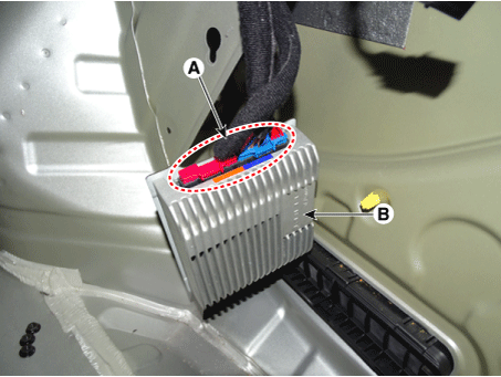
Loosen the nuts (A) on the amplifier.
Tightening torque:
3.9–5.8 N·m (0.4–0.6 kgf·m, 2.8–4.3 ft-lbf, 34.7–52.0 in-lbf)
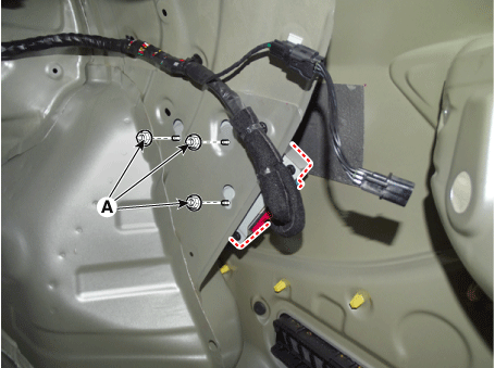
Remove the amplifier (B) after disconnecting the connector (A).
[5DR]
Remove the subwoofer.
(Refer to AVN System - "Speaker")
Loosen the nuts (A) on the amplifier.
Tightening torque:
3.9–5.8 N·m (0.4–0.6 kgf·m, 2.8–4.3 ft-lbf, 34.7–52.0 in-lbf)
Remove the amplifier (B) after disconnecting the connector (A).
Installation
Install in the reverse order of removal.
Inspection
In the body electrical system, faults can be quickly diagnosed using the Korean Diagnostic System (KDS).
Self-Diagnosis: Malfunction and code number check (DCT).
Current Data: Check the system input/output status.
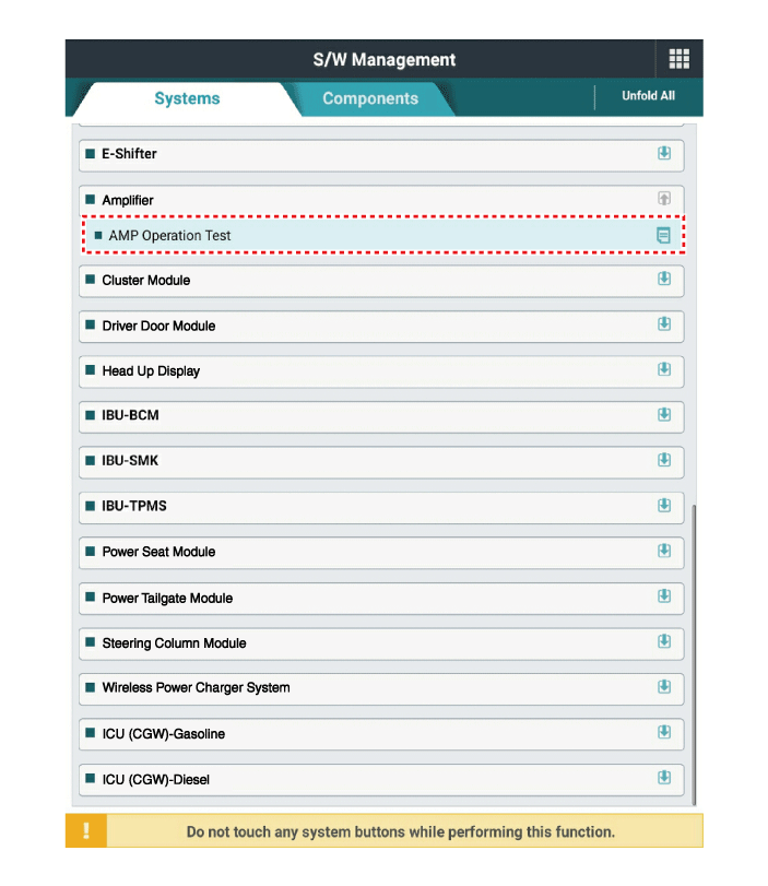
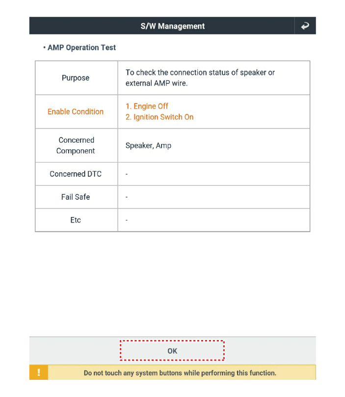
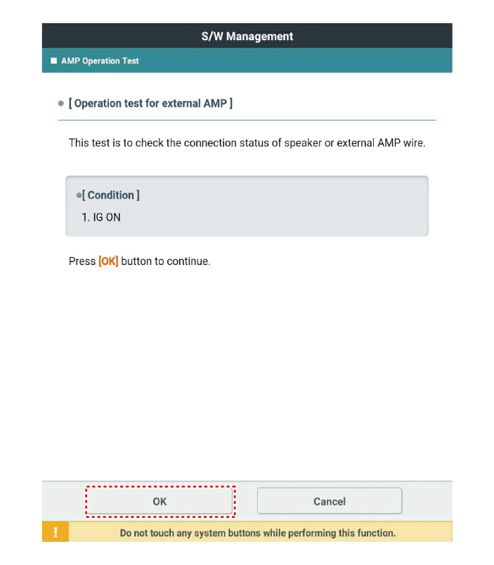
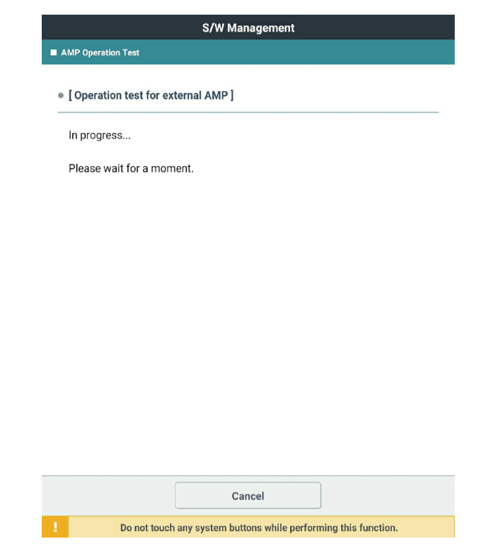
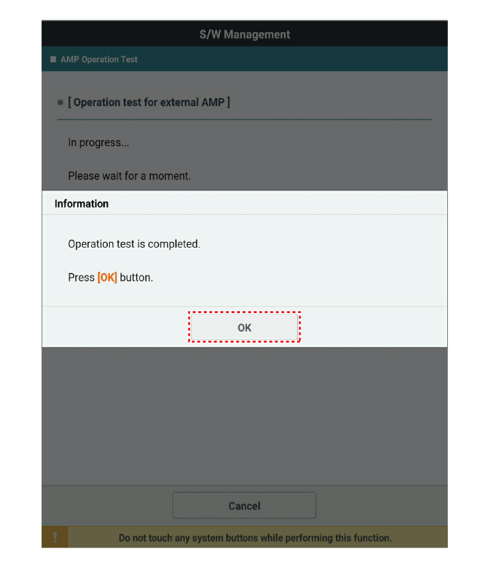
Operation check: Check the operating status of the system.
Additional function: Control of other functions, including the setting parameter system and zero point adjustment.
Select the "Vehicle Model" and the system to be checked in order to inspect the vehicle with the scan tool.
Select "Amplifier" to check the AVN.
Select the "Current Data" menu to view the current input/output data status.
The input/output data for the sensors corresponding to the Amplifier can be checked.
Test yourself
A quick Kia Forte BD quiz: every answer comes with an explanation and a link to the manual page.