Body Electrical System
AVN Head Unit
In this manual: Body Electrical System
7steps
~42min
2/5difficulty
Done 0 of 7
Components and Component Location
Components
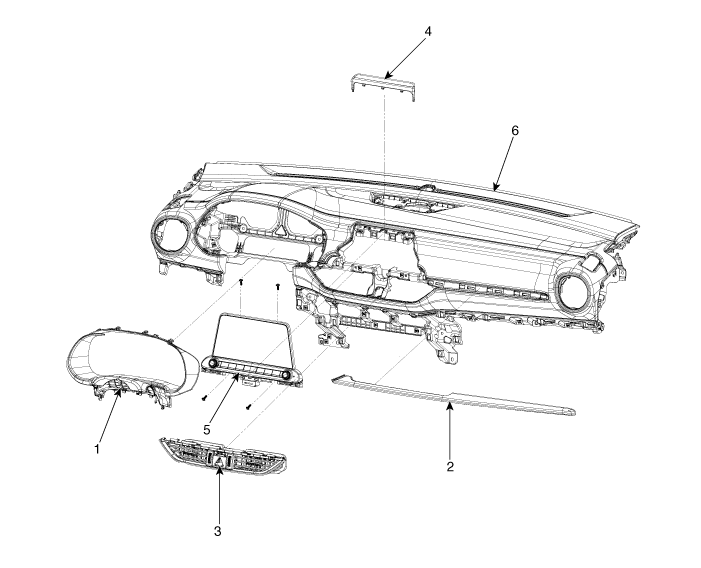
| 1. Cluster Fascia Panel 2. Crash Pad Center Garnish 3. Center Air Vent Assembly |
4. AVN Upper Panel 5. AVN Head Unit 6. Crash Pad |
Circuit Diagrams
Connector and Terminal Function
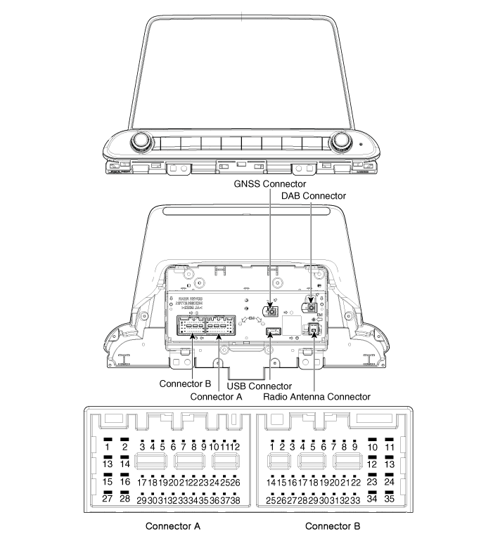
| No. | Connector A | Connector B | |
| External amplifier | Internal Amplifier | ||
| 1 | - | Left rear door speaker (+) | - |
| 2 | - | Left rear door speaker (-) | MIC (+) |
| 3 | Voice navigation amplifier (+) | - | - |
| 4 | Amplifier_SPDIF (High) | - | - |
| 5 | - | Antenna Power | |
| 6 | RVM Camera: Power | Illumination (+) | |
| 7 | RVM Camera: Video | Multimedia CAN (High) | |
| 8 | - | - | |
| 9 | - | - | |
| 10 | AUX Audio right_input | Battery (+) | |
| 11 | AUX Detection | Battery (+) | |
| 12 | Steering Wheel Remote Control | Ground | |
| 13 | - | Left front door speaker (+) | Ground |
| 14 | - | Left front door speaker (-) | - |
| 15 | - | Right front door speaker (-) | MIC (-) |
| 16 | - | Right front door speaker (+) | - |
| 17 | Voice navigation amplifier (-) | - | - |
| 18 | Amplifier SPDIF (Low) | - | - |
| 19 | SPDIF Amplifier (Ground) | - | Illumination (-) |
| 20 | RVM Camera: Ground | Multimedia CAN (Low) | |
| 21 | RVM Camera: Video Ground | - | |
| 22 | - | ACC | |
| 23 | - | - | |
| 24 | AUX Audio Left Input | - | |
| 25 | AUX audio ground | Provide Regression | |
| 26 | Steering Wheel Remote Control (Ground) | - | |
| 27 | - | Right rear door speaker (-) | - |
| 28 | - | Right rear door speaker (+) | - |
| 29 | - | - | |
| 30 | - | - | |
| 31 | - | - | |
| 32 | - | - | |
| 33 | RVM Camera: Screen Ground | IGN1 | |
| 34 | - | - | |
| 35 | - | - | |
| 36 | - | ||
| 37 | - | ||
| 38 | Vehicle Speed | ||
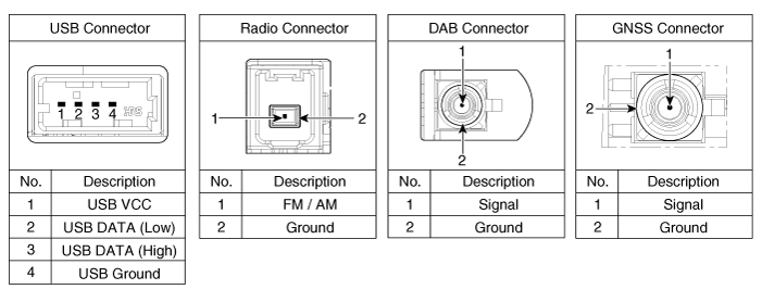
Repair Procedures
Removal
Disconnect the negative (-) battery terminal.
Remove the cluster fascia.
(Refer to Body — "Instrument Panel")
Remove the center air vent assembly (B) after removing the cushion pad garnish (A).
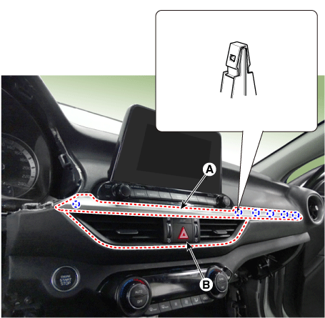
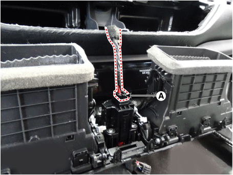
Disconnect the connector of the center air vent assembly (A).
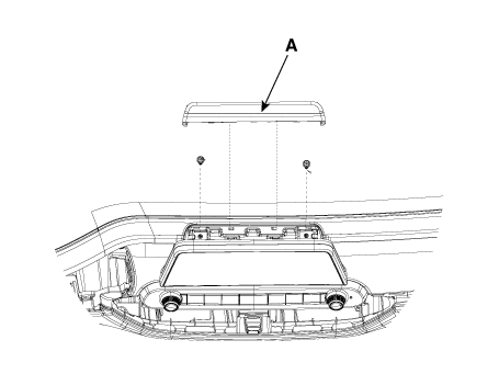
Loosen the screws after removing the AVN upper panel (A).
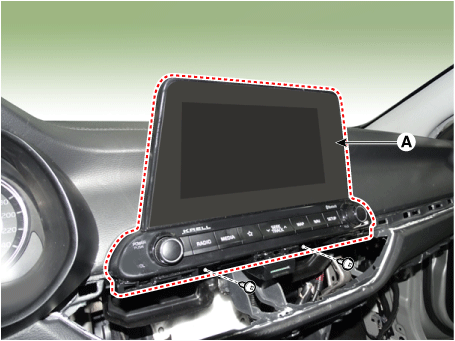
Remove the AVN head unit (A) after loosening the screws.
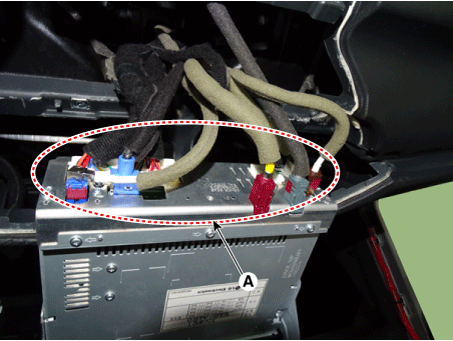
Disconnect the connectors (A) from the AVN head unit.
Installation
Install in the reverse order of removal.
Test yourself
A quick Kia Forte BD quiz: every answer comes with an explanation and a link to the manual page.
Was this page helpful?