Wireless Power Charger (WPC)
Specifications
Specifications
| Items | Specification |
| Rated Voltage | 13.5 V DC |
| Operating Voltage | 8.5–16.0 V DC |
| Operating Temperature | -22 to 167 °F (-30 to +75 °C) |
| Dark Current | MAX. 1 mA |
| Output Power | 5 W |
| Output Frequency | 110 ± 5 kHz |
Description and Operation
Description
Wireless Charging System
During ACC or IG ON, battery voltage is supplied to the wireless power charger system to transmit an output power of 5 W to the mobile phone.
Mobile phones certified to the WPC wireless charging standard (Qi 1.2.2) or exclusive wireless charging cases can be used.
Wireless Charging System Block Diagram

Vehicle power supply.
Convert to AC. Generate an electromagnetic field in the 1st coil.
Generate induced current in the power receiver by electromagnetic induction.
Generate AC current in the 2nd coil.
Convert to DC.
Charge the battery.
System Configuration Diagram
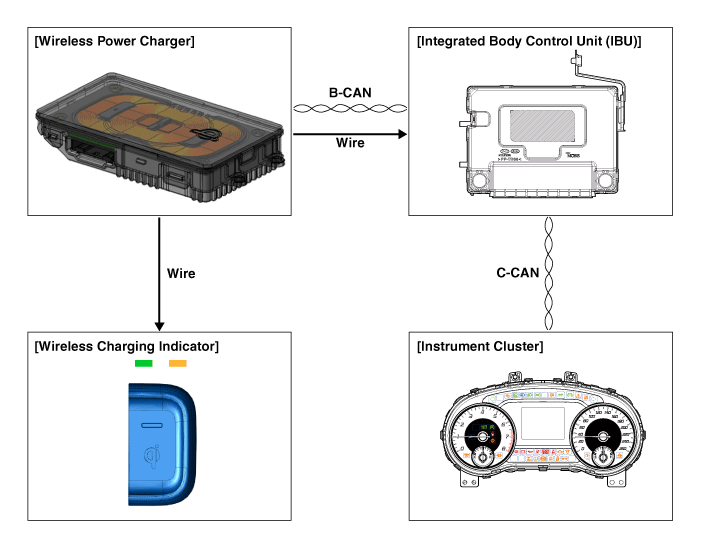
Instrument cluster: Mobile phone contact alerts.
Wireless charging indicator: Displays the charging status.
Integrated Body Control Unit (IBU):
Detects contact with the mobile phone.
Stops charging while LF is activated.
Main Functions of the Wireless Charger System
Charging Function
Activation Method
a. Close all vehicle doors.
b. Turn the vehicle power to ACC or IG ON.
b. Place the mobile phone with wireless charging function on the tray.
Charging Status Display
Mode Charging LED Display NOTE Charging Ready LED off 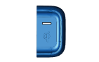
Charging in progress Yellow LED on 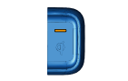
Charging complete Green LED on 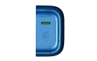
Charging error Yellow LED flashing 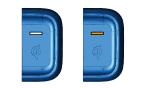
Blinks 10 times over 10 seconds, then the LED turns off for 50 seconds (60 seconds total).
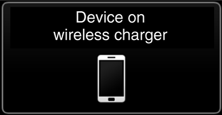
Mobile Phone Left Behind Alert Function
Activation Method
a. Key OFF while the phone is still charging.
b. Check whether the phone is on the wireless charging pad.
b. A quick notification is displayed on the instrument panel that the phone was left in the vehicle if a door is opened and the phone is left in the vehicle, or the phone is left in the vehicle for more than 1 minute (approx. 4-5 seconds).
Overheating Prevention
Activation Method
a. If the thermistor temperature inside the wireless charging module rises above a set level (158 °F (70 °C)), charging stops to protect the mobile phone battery.
b. When the thermistor temperature drops below a set level (149 °F (65 °C)), charging resumes.
Foreign Object Detection
Charging stops if a coin or other metallic object is between the wireless charger and the mobile phone.
[Foreign Object]
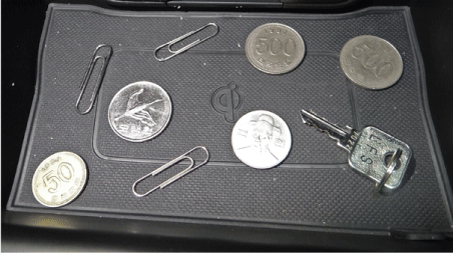
When the system detects a foreign object and stops charging the mobile phone, the wireless charging function resumes immediately after the foreign object is removed.
IBU Frequency Interference Prevention Unit
This function prevents interference between the wireless charging frequency and the smart key frequency band.
Wireless charging stops when the door is open or the IBU is in LF (smart key search) mode.
For example, the wireless charging function stops if the driver carries the smart key out of the vehicle while the ignition is on.
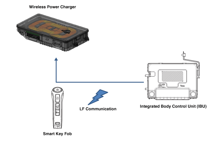
It returns to normal operation when the IBU LF mode ends.
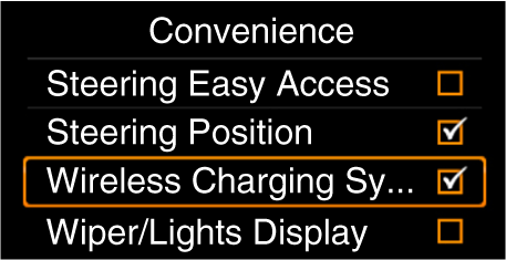
Turn the wireless charging function on or off using the USM.
※ Trunk refers to models with a trunk lid.
Wireless Charging System Protection
| Item | Condition | Status |
| Protects against low/high voltage | Protects and stops charging when voltage is below 8.5 V or above 16.5 V. | LED is off (stops operation) |
| Charging above 9.0 V and below 16.0 V. | ||
| Protects against reverse voltage | Protects and stops charging in case of reverse voltage | LED is off (stops operation) |
| Protects against overcurrent | Protects and stops charging when 4.5 A is detected | Yellow LED flashing |
| Protects against overheating | Protects and stops charging when the internal temperature sensor of the wireless charging module detects 158°F (70°C) | Yellow LED flashing |
| Resumes when temperature is below 149°F (65°C) | ||
| Foreign object (coins, paper clips, precious metals, etc.) |
Protects and stops charging when a foreign object is detected (overheating prevention) | Yellow LED flashing |
| Prevents frequency interference | Protects and stops charging by activating the SMK if the door or trunk is open. | LED is off (stops operation) |
| Resumes 3.5 seconds after all doors and the trunk are closed and SMK operation is complete. | ||
| Mobile Phone Contact Warning | If a smartphone is on the charging pad when a door is opened after the ignition is OFF. | Displays a warning message on the instrument cluster (approximately 4-5 seconds) |
※ Trunk refers to models with a trunk lid.
Circuit Diagrams
Connector and Terminal Function
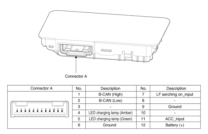
Schematic Diagram
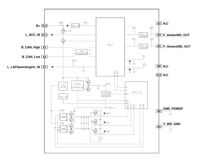
Repair Procedures
Removal
Disconnect the negative (-) battery terminal.
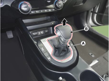
Remove the handle (B) by pulling it in the direction of the arrow after separating the dust covers (A) from the upper console cover.
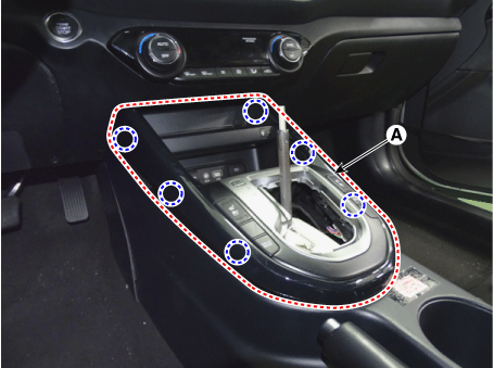
Remove the upper console cover (A).
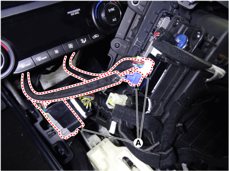
Disconnect the connector (A) from the upper console cover.
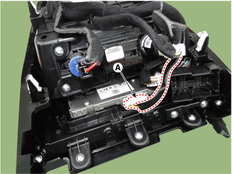
Disconnect the connector (A) from the wireless charger.
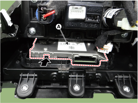
Remove the wireless charger (A) by pressing the retaining hooks.
Installation
Install in the reverse order of removal.
Inspection
Body electrical system malfunctions can be diagnosed more quickly using the Kia Diagnostic System (KDS).
KDS provides the following information.
Self-diagnosis: Checks and displays diagnostic trouble codes (DTC).
Data list: Checks the input/output values of the system.
Active test: Checks the operating condition of the system.
Additional functions: System option control, zero point adjustment, and other functions.
To diagnose the vehicle with diagnostic equipment, select "Vehicle Model" and "Wireless Charger System" to be checked.
To check the current input/output values, select "Sensor Data" from the menu.
The input/output sensor values corresponding to the selected module can be checked.
To forcibly activate the selected module input, select "Actuation Test".
To determine the cause of a fault in each module using self-diagnosis, select "Diagnostic Trouble Code".
Test yourself
A quick Kia Forte BD quiz: every answer comes with an explanation and a link to the manual page.