Check brake operation by applying the brakes during a test drive. If the brakes do not work properly, check the brake booster. Replace the brake booster as an assembly if it does not work properly or if there are signs of leakage.
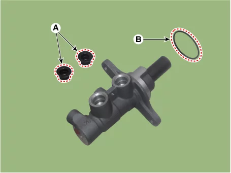
Piston cup and pressure cup inspection (B)
Check the brake operation by applying the brake. Observe damage or oil leakage. Replace the brake booster assembly if it is not operating properly or is damaged or leaking.
Check for a difference in brake pedal stroke between quick and slow brake applications. Replace the master cylinder if there is a difference in pedal stroke.
Brake hose (C)
Check for damage or leakage. Look for damage or signs of fluid leakage. Replace the brake hose with a new one if it is damaged or leaking.
Caliper piston seal and piston boots (D)
Check brake operation by applying the brakes.and look for damage or signs of fluid leakage. If the pedal does not work properly, the brakes drag, or there is damage or signs of fluid leakage, disassemble and inspect the brake caliper. Replace the boots and seals with new ones whenever the brake caliper is disassembled.
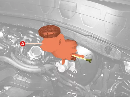
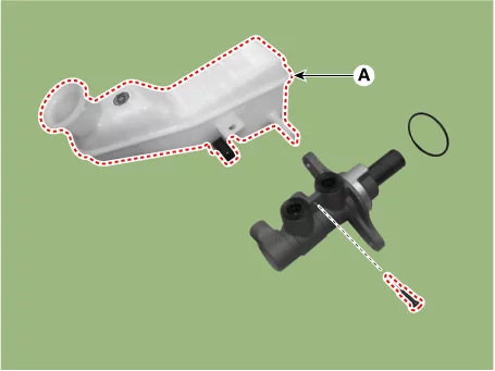
Brake Master Cylinder Components and Components Location
Run the engine for 1 to 2 minutes before stopping. It is normal for pedal strokes to gradually decrease as the pedal is pressed several times. If the brake pedal stroke is constant, check the brake check valve, vacuum hose, brake booster.
Press the brake pedal with the engine stationary, and then start the engine. if the brake pedal moves downwards it is normal and abnormal if the brake pedal does not move.
With the engine running, press the brake pedal and stop the engine. Hold the pedal pressed for 30 seconds. If the brake pedal height does not change, it is normal, and if the brake pedal height has risen, check the brake check valve, vacuum hose, and brake booster.
If the brake booster meets all 3 steps above, the brake booster is OK. if even one step fails, check the check valve, vacuum hose, and brake booster.
Brake Booster Removal and Installation - G 1.6 MPI GAMMA
Removal and Installation
Turn ignition switch OFF and disconnect the negative (-) battery cable.
Remove the engine control module (ECM). (Refer to Engine Control / Fuel System - "Engine Control Module (ECM)")
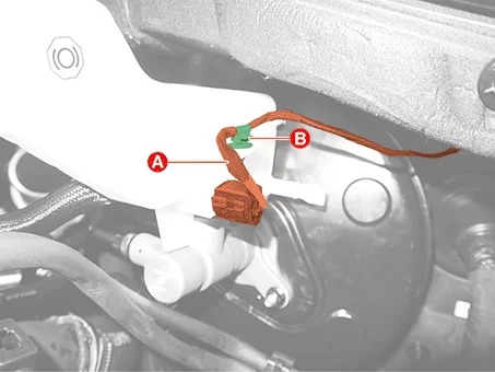
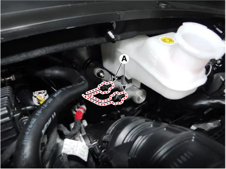
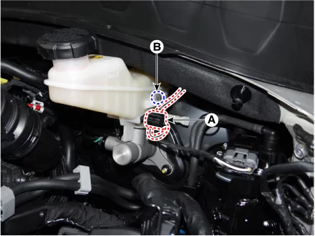
Disconnect the brake fluid level sensor connector (A) and wiring fastener (B).
Separate the brake tube (A) from the master cylinder by loosening the tube flare nut.
Tightening torque : 18.6 - 23 N·m
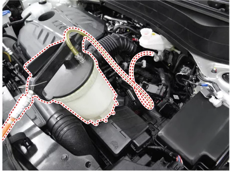
Remove the brake fluid from the master cylinder reservoir with a syringe.
Do not spill brake fluid on the vehicle as it may damage the paint. If brake fluid comes in contact with the paint, wash off immediately with water.
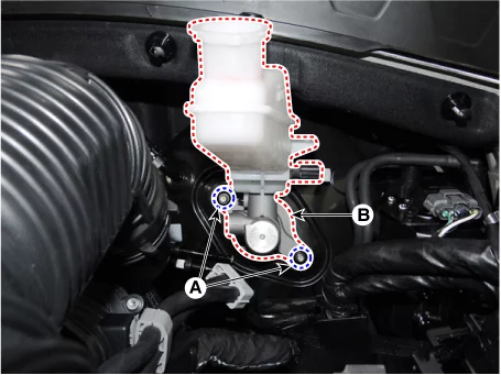
Remove the master cylinder (B) from the brake booster after loosening the mounting nuts (A).
Tightening torque: 9.8 - 15,7 N·m
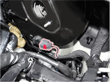
Disconnect the vacuum sensor connector (A).
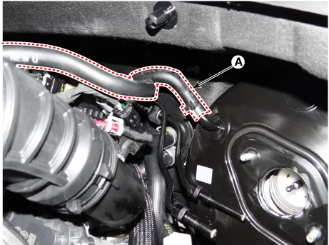
Disconnect the brake vacuum hose (A).
Remove the crash pad lower panel. (Refer to Body - "Crash pad lower panel")
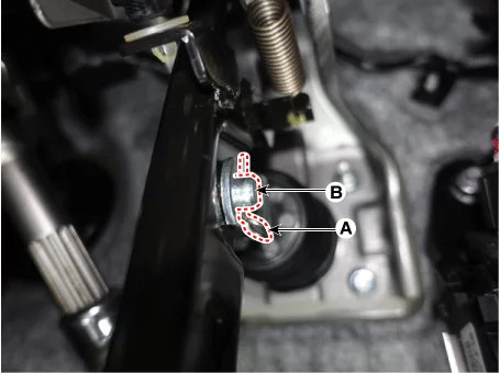
Remove the snap pin (A) and clevis pin (B).
Before installing the pin, apply the grease to the joint pin.
Use a new snap pin whenever installing.
Remove the brake booster mounting nuts (A).
Tightening torque : 16.7 - 26 N·m
Remove the brake booster (A).
Install in the reverse order of removal.
After installation, bleed the brake system. (Refer to Brake system - "Brake Bleeding Procedures")
Brake Booster Removal and Installation - G 1.6 T-GDI GAMMA ll
Removal
Since there is a risk of injury due to high pressure fuel leakage, do not perform any work right after the engine is stopped.
Some residual fuel may be released, so cover the connection with a cloth or the like before disconnecting the fuel line.
Remove the engine room under cover. (Refer to Engine Mechanical System - "Engine Room Under Cover")
Release the residual pressure in fuel line. (Refer to Fuel Delivery System - "Release Residual Pressure in Fuel Line")
Remove the brake master cylinder. (Refer to Brake System - "Brake Master Cylinder")
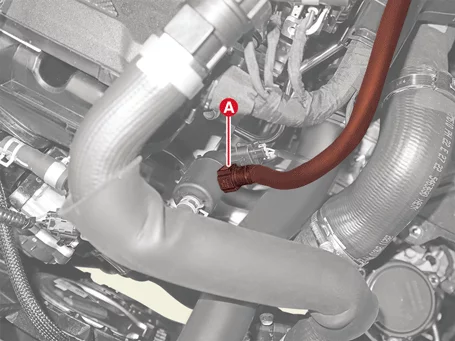
Separate the vapor tube (A).
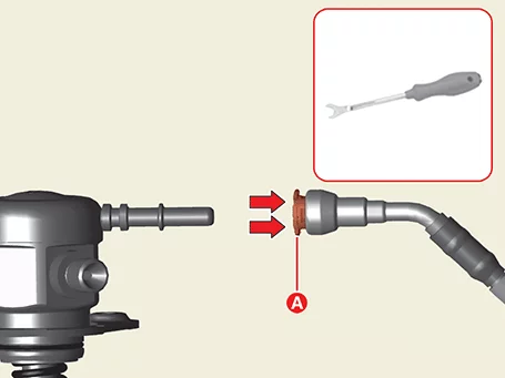
Separate the low pressure fuel feed tube (A).
Cover the connection with a clean cloth since the residual fuel may be released after "Release Residual Pressure in Fuel Line" procedures.
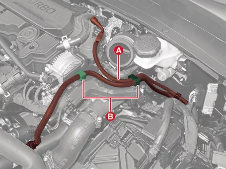
When separating the fuel supply tube, separate it after pressing the holder (A) firmly by using the clip remover.
Separate the fuel lines (A) after separating the holders (B) from the brackets.
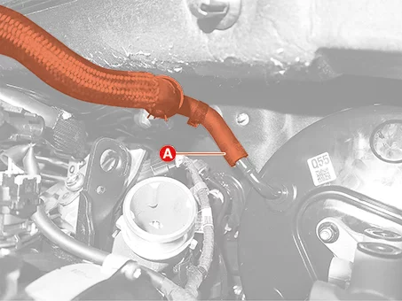
Release the clamp, and then disconnect the brake vacuum hose (A).
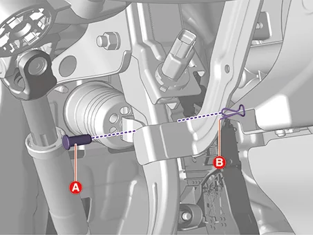
Separate the brake pedal arm clevis pin (A) and the split pin (B).
Do not reuse the split pin.
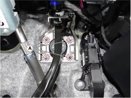
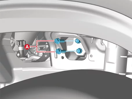
Remove the brake member assembly nuts (A).
Tightening torque : 16.7 - 26 N·m
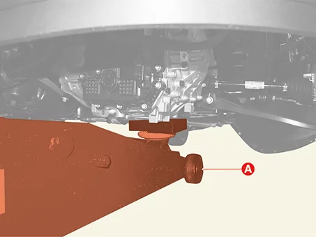
Support the automatic transaxle by using a tool such as a garage jack (A).
Remove the automatic transaxle mounting bracket bolts (A).
Tightening torque : 107.9 - 128 N·m
Down the automatic transaxle (A) by lowering the jack.
Excessive lowering of the automatic transmission (A) may damage the engine mounting.
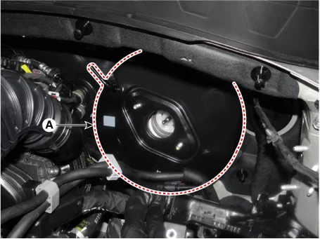
Remove the brake booster (A).
Be careful not to damage any surrounding parts when removing or installing the brake booster (A).
Installation
Install in reverse order of removal.
Be careful not to twist the brake vacuum hose when installing.
Apply the grease when installing the brake pedal arm clevis pin (Grease type : GREASE PDLV-1)
Be careful not to change the mounting position of the clevis pin and split pin.
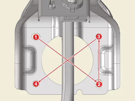
To minimize damage to the thread and brake member assembly during installation, tighten all nuts with hands and then tighten them to the tightening torque values in the order shown below.
Fill the brake reservoir with brake fluid and perform the brake bleeding procedure. (Refer to Brake System - "Brake Bleeding Procedures")
Check the brake fluid leakage and pedal operating condition.
Brake Booster Removal and Installation - G 2.0 MPI NU
Removal
Remove the brake master cylinder. (Refer to Brake System - "Brake Master Cylinder")
Release the clamp, and then disconnect the brake vacuum hose (A).
Remove the brake pedal arm mounting clevis pin (A) and split pin (B).
Do not reuse the split pin.
Remove the brake member assembly nuts (A).
Tightening torque : 16.7 - 26 N·m
Remove the brake booster (A).
Be careful not to damage any surrounding parts when removing or installing the brake booster (A).
Installation
Install in reverse order of removal.
Be careful not to twist the brake vacuum hose when installing.
Apply the grease when installing the brake pedal arm clevis pin (Grease type : GREASE PDLV-1)
Be careful not to change the mounting position of the clevis pin and split pin.
To minimize damage to the thread and brake member assembly during installation, tighten all nuts with hands and then tighten them to the tightening torque values in the order shown below.
Fill the brake reservoir with brake fluid and perform the brake bleeding procedure. (Refer to Brake System - "Brake Bleeding Procedures")
Check the brake fluid leakage and pedal operating condition.
Brake Booster Inspection
Inspection
Check the check valve inside the vacuum hose.
Do not disassemble the check valve from the vacuum hose.
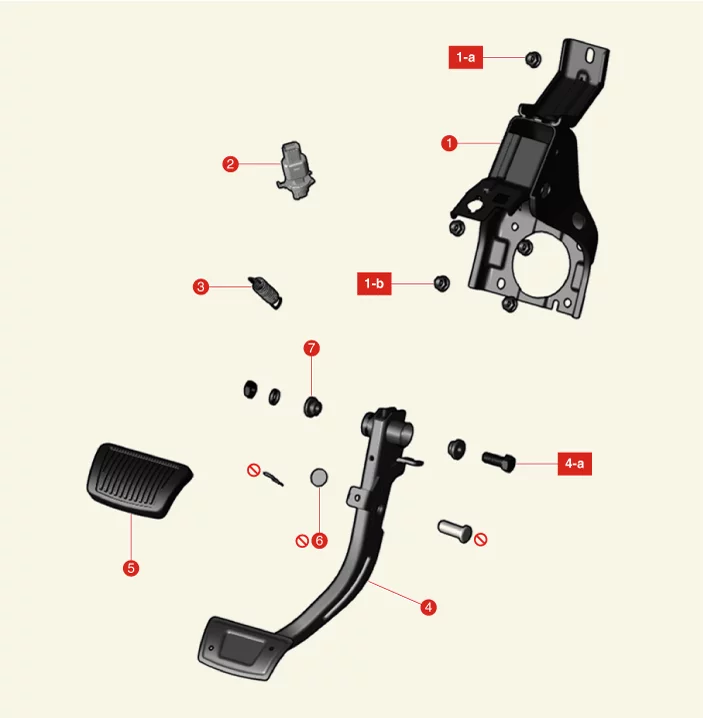
4. Brake Pedal Arm 4-a. 24.5 - 34 N·m 5. Brake Pedal Pad 6. Pedal Stopper 7. Brake Pedal Arm Bushing
Brake Pedal Removal and Installation
Removal
Disconnect the battery negative ( - ) terminal.
Remove the crash pad lower panel. (Refer to Body - "Crash Pad Lower Panel")
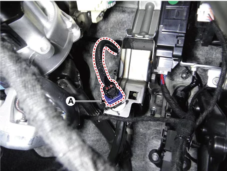
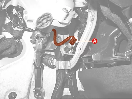
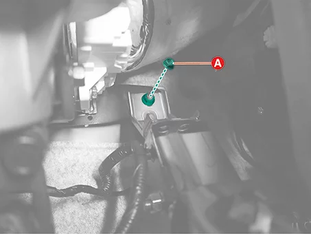
Disconnect the stop lamp switch connector (A).
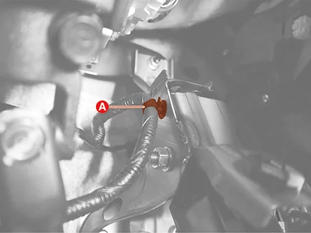
Remove the stop lamp switch connector wiring fastener (A).
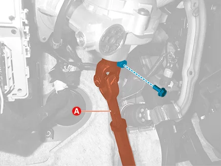
Separate the universal joint assembly (A) from the MDPS column and housing after removing the bolt.
Tightening torque : 49.0 - 52 N·m
Do not reuse the universal joint assembly bolt.
Separate the brake pedal arm clevis pin (A) and the split pin (B).
Do not reuse the split pin.
Remove the brake pedal member assembly nuts (A).
Tightening torque : 16.7 - 26 N·m
Remove the brake pedal assembly after removing the nut (A),
Tightening torque : 16.7 - 26 N·m
Installation
Install in reverse order of removal.
Apply the grease when installing the brake pedal arm clevis pin (Grease type : GREASE PDLV-1)
Be careful not to change the mounting position of the clevis pin and split pin.
To minimize damage to the thread and brake member assembly during installation, tighten all nuts with hands and then tighten them to the tightening torque values in the order shown below.
Check the brake pedal operating normally after installation.
Check brake fluid leakage and pedal operation.
Brake Pedal Inspection
Inspection
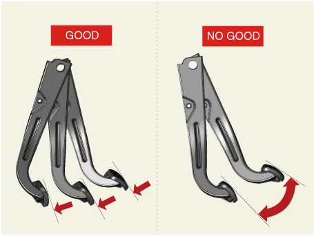
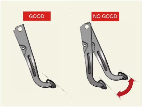
Check if the brake pedal is damaged.
Check if the relevant parts are cracked, or damaged.
Inspect the stop lamp switch. (Refer to Brake System - "Stop Lamp Switch")
Stop Lamp Switch Components and Components Location
4. Brake Pedal Arm 4-a. 24.5 - 34 N·m 5. Brake Pedal Pad 6. Pedal Stopper 7. Brake Pedal Arm Bushing
Stop Lamp Switch On Vehicle Inspection
On Vehicle Inspection
The brake system can be more quickly diagnosed for problems by using the KDS (Refer to "DTC guide").
Self diagnosis : Inspection and display fault code (DTC) (Refer to DTC guide when fault code is found.)
Refer to the KDS screen for operating conditions and details.
Stop Lamp Switch Description and Operation
Description and Operation
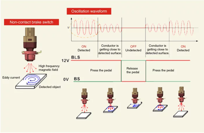
Operation principle of inductive non-contact switch
Use the high-frequency magnetic field and the induced current that is generated by oscillation (to approved voltage) of the coil in the switch.
The eddy current is generated on surface of metal by self inductance effect if there is metal in high frequency magnetic field.
The eddy current that is generated decreases the high frequency magnetic field as much as amount of generated by disturbing the switch's magnetic flux.
ON-OFF by determining whether high voltage magnetic field is decreases or not(calculate the voltage difference by length between metal and coil).
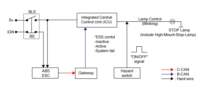
Stop Lamp Switch Circuit Diagram
Schematic Diagram
Circuit Diagram
Stop Lamp Switch Troubleshooting
Troubleshooting
Part diagnosis
Name
Suspected Cause
Symptom
Correction Method
Switch fuse
Faulty fuse connection, Damaged fuse
DTC code : (Refer to "DTC guide")
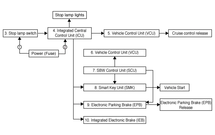
Shifting gear trouble, Starting failure, Cruise control function cancelation trouble, EPB function cancelation trouble, Stop lamp lighting trouble, ESC OFF light illuminated.
A waveform inspection is performed using an oscilloscope on each part during vehicle acceleration/braking. (Refer to stop lamp switch circuit inspection procedures)
Refer to the relevant repair procedures of the part when something abnormal is discovered in the waveform (Refer to the repair procedures of the relevant part and if necessary replace it)
Relay fuse
Faulty fuse connection, Damaged fuse
DTC code : (Refer to "DTC guide")
Shifting gear trouble, Starting failure, Cruise control function cancelation trouble, EPB function cancelation trouble, Stop lamp lighting trouble, ESC OFF light illuminated.
Stop lamp switch
Damaged wiring of each part
Faulty connection to connector
Each part is defective
DTC code : (Refer to "DTC guide")
Shifting gear trouble, Starting failure, Cruise control function cancelation trouble, EPB function cancelation trouble, Stop lamp lighting trouble , ESC OFF light illuminated.
Stop signal electronic module (If it applies)
DTC code : (Refer to "DTC guide")
Symptom : Shifting gear trouble, Starting failure, Cruise control function cancelation trouble, EPB function cancelation trouble, Stop lamp lighting trouble , ESC OFF light illuminated.
Engine Control Module (ECM)
DTC code : (Refer to "DTC guide")
Symptom :Shifting gear trouble,Cruise control function cancelation trouble
Integrated Body Control Unit (IBU)
Shifting gear trouble
Inhibitor Switch
DTC code : (Refer to "DTC guide")
Symptom : Shifting gear trouble, Starting failure, Cruise control function cancelation trouble, EPB function cancelation trouble
Smart Key Unit (SMK)
Faulty engine start
Electronic Parking Brake(EPB)
Electronic Parking Brake (EPB)
ABS/ESC control module (Pressure sensor)
ESC OFF light illuminated.
Symptom diagnosis
Symptom
Suspected Causes
Correction Method
Faulty engine start
Switch fuse, Relay fuse, Stop lamp switch, Stop signal electronic module, ABS/ESC control module, Each wire, Connector
Inspect waveform using an oscilloscope on each part during vehicle acceleration/braking. (Refer to stop lamp switch circuit inspection Procedures)
Refer to the relevant repair procedures of the part when something abnormal is discovered in the waveform (Refer to the repair procedures of the relevant part and if necessary replace it)
Shifting gear trouble
Switch fuse, Relay fuse, Stop lamp switch, Stop signal electronic module, IBU, ECM, Inhibitor switch, Each wire, Connector
ESC OFF light illuminated
Switch fuse, Relay fuse, Stop lamp switch, Stop signal electronic module, ABS/ESC control module, Each wire, Connector
P0504
Switch fuse, Relay fuse, Stop lamp switch, Stop signal electronic module, ECM, Each wire, Connector
Stop lamp not working
Switch fuse, Relay fuse, Stop lamp switch, Stop signal electronic module, ECM, Each wire, Connector
Stop lamp always on
Stop lamp switch, Stop signal electronic module, Wiring short circuit, Damaged fuse
Refer to DTC guide when the related DTC codes are displayed.
Stop Lamp Switch Replacement
Replacement
Disconnect the battery negative ( - ) terminal.
Remove the crash pad lower panel. (Refer to Body - "Crash Pad Panel")
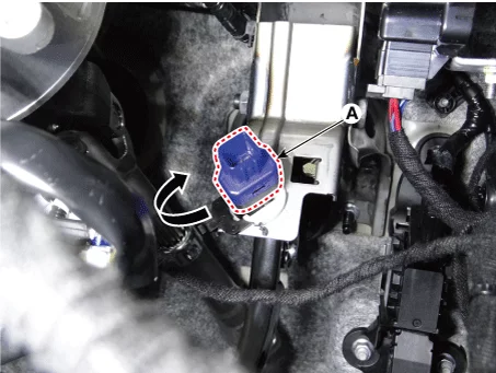
Disconnect the stop lamp switch connector (A).
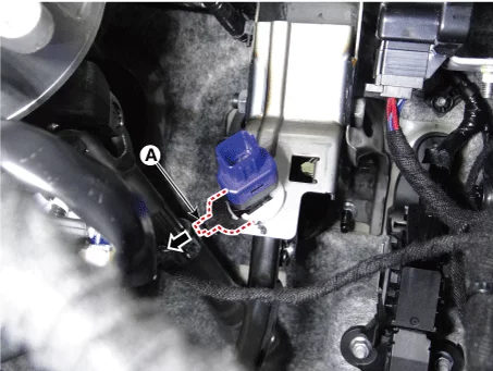
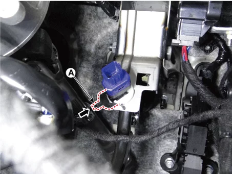
Pull the locking plate (A) in the direction of the arrow.
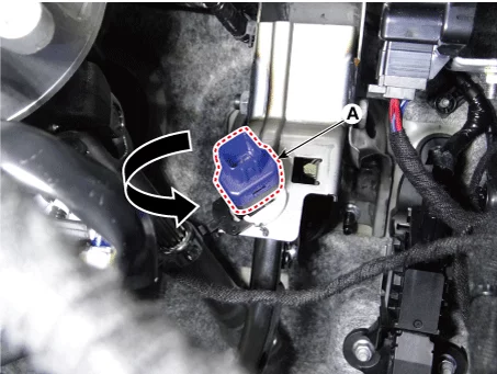
Turn the stop lamp switch (A) counterclockwise about 45 degrees and remove it.
A confirmation can be made to see if the connector has been secured properly and if a connection mark is present.
Insert the stop lamp switch (A) until the contact part is invisible, and rotate it clockwise at 45° to install it to the brake pedal.
Push the locking plate (A) in the direction of the arrow to install it.
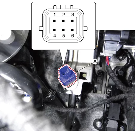
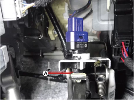
Check the gap (A) between the stop lamp switch and the brake pedal stopper.
Disc Cleaning before Inspection The rust caused by leaving the vehicle unattended for a long period of time is naturally removed under normal driving conditions. It may affect thickness and runout measurements, please remove rust on the brake disc for accurate measurements.
Check the brake disc for rust.
Spray the cleaning solution on rusted surface of disc.
Cleaning solution : Water (300 ml) + Detergent (15 ml)
Do not use lubricating, oil-based cleaning agents (wax, rust inhibitors). Poor braking performance and risk of fire due to pad friction during braking.
Drive the vehicle up to 30 mph and depress the brake up to stop for complete repeat more than 5 cycles.
Clean the brake disc with clean water.
Check the brake disc for rust.
If rust is not removed, repeat the above procedure again.
Remove the front wheel and tires. (Refer to Suspension System - "Wheel")
Check the brake disc for damage.
Measure the brake disc thickness (A) and run-out using the micro meter and dial gauge at least 24 locations on the same column along the lines shown in the figure below. Front Brake Disc Thicknes Standard for 15 inch wheel disc : 23.0 mm (0.90 in.) for 16 in wheel disc : 25.0 mm (0.98 in.) Service Limit for 15 inch wheel disc : 21.4 mm (0.84 in.) for 16 inch disc : 23.4 mm (0.92 in.) DTV (Disc Thickness Variation) : 0.015 mm (0.0005 in.) [Circumference, Radial direction]
If the thickness difference between each measuring part is greater than standard, resurface or replace the brake disc.
Resurface the brake disc according to the method of using the equipment in possession.
If the brake disc is less than or equal to the limit, replace the brake disc with a new one.
Install the front wheel and tires. (Refer to Suspension System - "Wheel")
Remove the front wheel and tires. (Refer to Suspension System - "Wheel")
Install the dial gauge perpendicular to the brake disc's external diameter of 10 mm (0.40 in.) and rotate the disc to measure the run-out.
Brake Disc Run Out Service Limit : 0.050 mm (0.0019 in.)
If the brake disc run-out exceeds the limit, resurface or replace the brake disc.
Resurface the brake disc according to the method of using the equipment in possession.
If the brake disc is less than or equal to the limit, replace the brake disc with a new one.
Install the front wheel and tires. (Refer to Suspension System - "Wheel")
Front Brake Disc Thickness Check Front Brake Disc Runout Inspection
Front Brake Disc Removal and Installation
Special Service Tool
Tool Name / Number
Illustration
Description
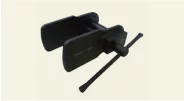
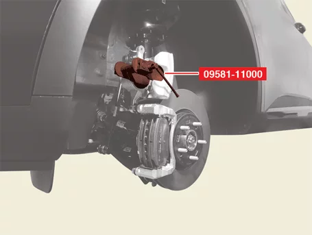
Piston expander 09581 - 11000
Spreading the front brake caliper piston.
Removal
Remove the front wheel and tires. (Refer to Suspension System - "Wheel")
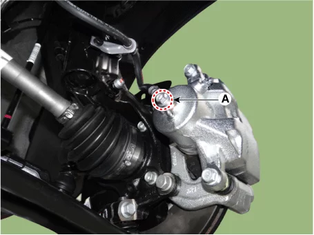
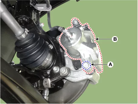
Remove the guide rod lower bolt (A) and then open the caliper body (B).
Tightening torque : 21.6 - 31 N·m
Remove the return springs (A).
Remove the brake pads (A).
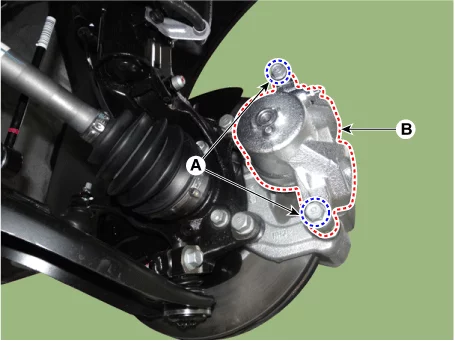
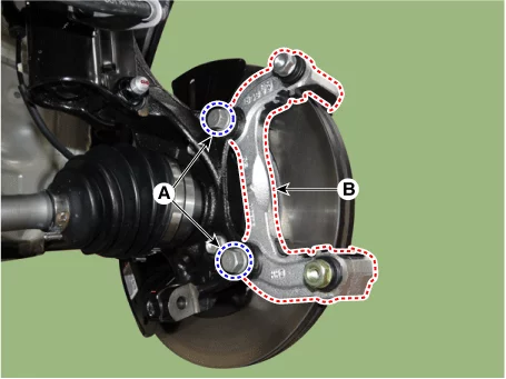
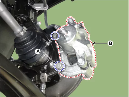
Remove the caliper assembly (B) after removing the caliper carrier bolts (A).
Tightening torque : 78.5 - 98 N·m
Secure the removed brake caliper body using a tool such as a cable tie.
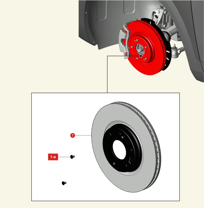
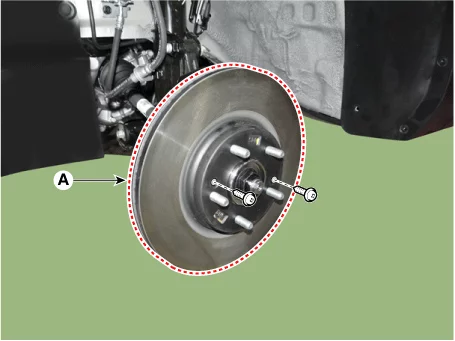
Remove the front brake disc (A) after removing the screws.
Tightening torque : 4.9 - 5,9 N·m
Installation
Install in reverse order of removal.
Be careful not to damage the piston when pressing it.
Be careful not to interfere with the piston when assembling the caliper body to the carrier.
Press the brake piston using SST (09581 - 11000) when installing the caliper body.
Depress the brake pedal several times to ensure that the brake pads are correctly positioned, then check operation.
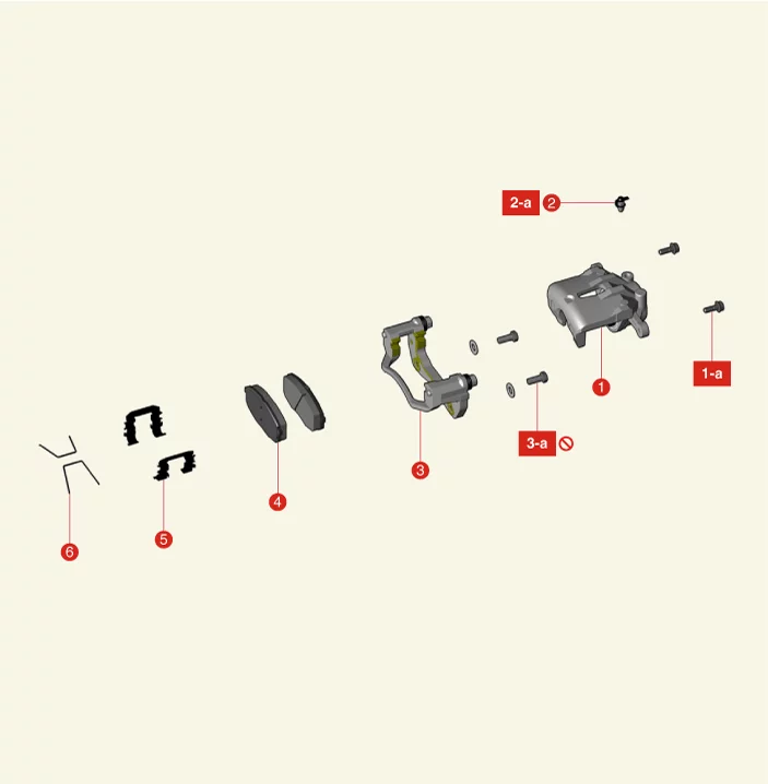
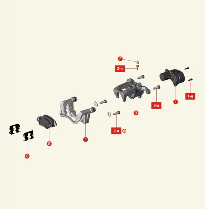
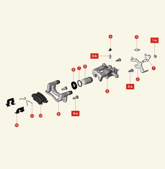
Rear Brake Caliper Components and Components Location
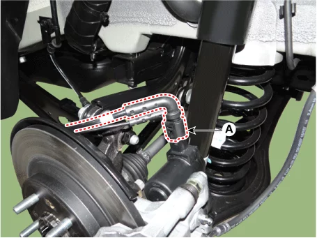
Release the parking brake. • EPB : Release the parking brake by using the KDS. (Refer to Brake System - "Electronic Parking Brake (EPB)") • None EPB : Release the hand lever parking brake fully.
Remove the rear wheel and tires. (Refer to Suspension System - "Wheel")
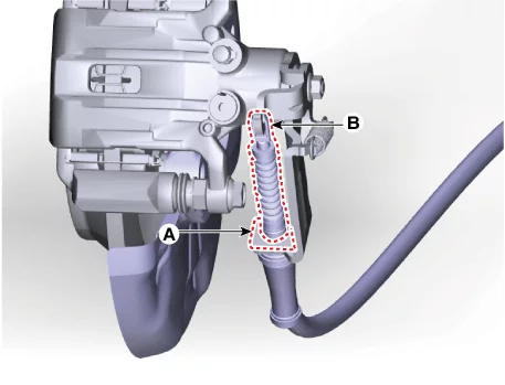
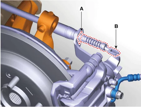
Disconnect the EPB actuator connector or parking brake cable. • EPB : Disconnect the EPB actuator connector (A). • None EPB : Remove the clip (A), and then separate the parking brake cable (B). [2WD] [4WD]
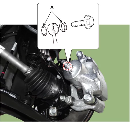
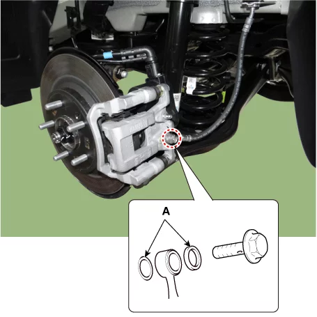
Separate the brake hose from the brake caliper after removing the brake hose bolt (A).
Tightening torque : 24.5 - 29 N·m
Do not reuse the washers (A) when installing the brake hose.
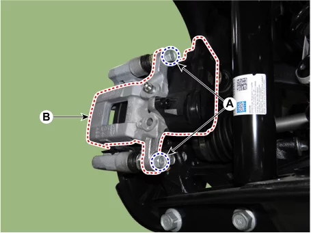
Remove the caliper body (B) after removing the guide rod bolt (A).
Tightening torque : 21.6 - 31 N·m
Remove the brake pads (A).
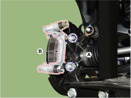
Remove the caliper carrier (B) after removing the bolts (A).
Tightening torque : 98.1 - 118 N·m
Do not reuse the caliper carrier bolts.
Installation
Install in reverse order of removal.
Be careful not to interfere with the piston when assembling the caliper body to the carrier.
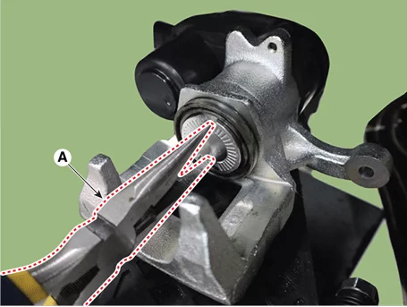
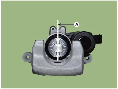
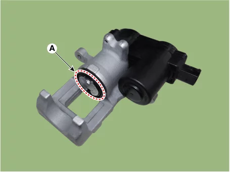
When installing the caliper body, turn the brake piston clockwise using a tool such as the long nose pliers (A) to press it in.
Check the piston groove position before installing the caliper body.
Fill the brake reservoir with brake fluid and perform air bleeding. (Refer to Brake System - "Brake Bleeding Procedures")
After installation, adjust the parking brake according to the parking brake specification.
EPB - (Refer to Parking Brake System - "Electronic Parking Brake (EPB)")
None EPB - (Refer to Parking Brake System - "Parking Brake Lever")
Depress the brake pedal several times to ensure that the brake pads are correctly positioned, then check operation.
Check the brake fluid leakage and pedal operating condition.
Check if the parking brake is operating normally.
Rear Brake Caliper Replacement
Replacement
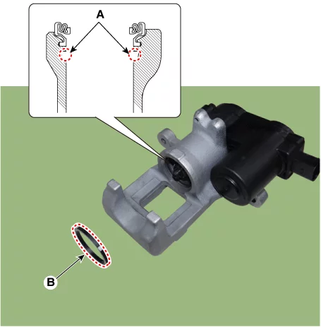
Rear Caliper Piston Boot and Seal
Do not reuse the piston boot and seal.
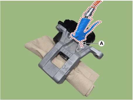
Put the clean cloth (A) between the caliper body and piston.
Inject compressed air (A) inside the caliper to depress the piston.
Be careful fingers or hands crush hazard when depressing the piston.
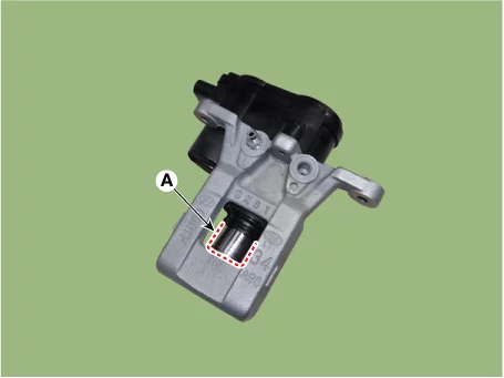
Remove the caliper piston (A).
Be careful not to damage the caliper piston and the inside of the cylinder.
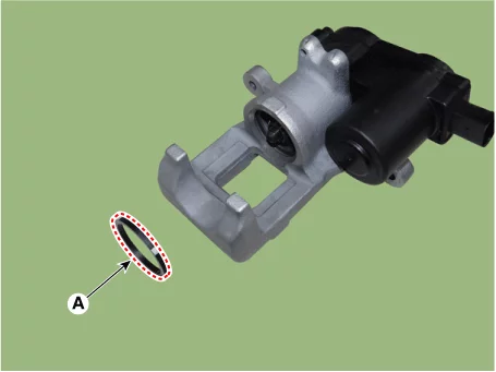
Remove the caliper piston boot (A).
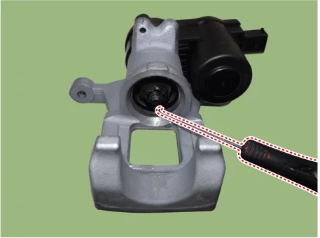
Remove the piston seal (A) using a screwdriver or a remover.
When using the tools, be careful not to damage the cylinder wall and piston seal groove.
Clean the inside of the caliper cylinder and the piston.
Insert the piston seal (B) to the cylinder seal groove (A).
Do not reuse the caliper piston seal.
Apply assembling oil on the piston seal (0.1 - 0.4 cc)
Be careful not to let foreign matter enter the cylinder.
Check that there are no dents or poor assembly of the piston seal.
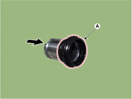
Insert the piston boot (A) in the direction of the arrow to the edge of the piston.
Do not reuse the piston boot.
Apply assembling oil on the piston boot.
Be careful not to damage the piston boot.
Be careful not to change the direction of the piston boot.
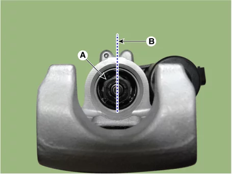
Turn the spindle nut (A) clockwise and push it all the way in, and check the position (B) of the spindle.
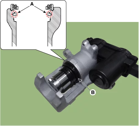
Insert the piston boot (B) into the caliper cylinder groove (A).
Be careful not to let foreign matter enter the cylinder.
Check the position (A) of the caliper piston groove and insert it into the cylinder.
When inserting the piston, be careful not to tilt the piston.
Be careful not to apply excessive force when inserting the piston.
Insert it slowly to prevent damage to the inside of the cylinder.
Insert the piston all the way in, and check the caliper piston boot (A) is installed properly.
Install the caliper body.
Fill the brake fluid to the 'MAX' line, and perform the brake bleeding procedures. (Refer to Brake System - "Brake Bleeding Procedures")
Depress the brake pedal several times to check that the brake fluid is not leaking.
Check that the parking brake is operating normally.
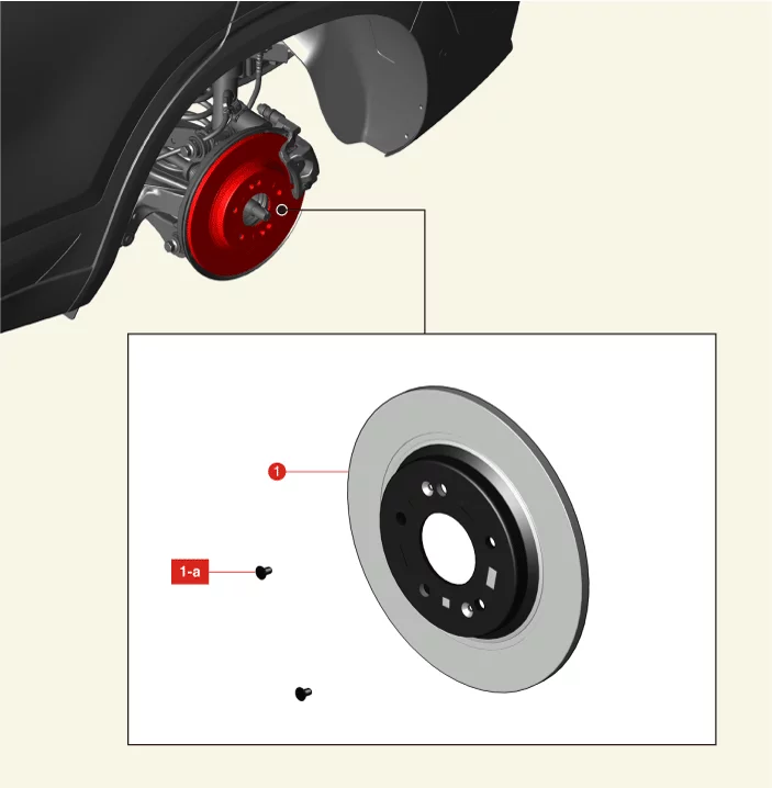
Rear Brake Disc Components and Components Location
Disc Cleaning before Inspection The rust caused by leaving the vehicle unattended for a long period of time is naturally removed under normal driving conditions. It may affect thickness and runout measurements, please remove rust on the brake disc for accurate measurements.
Check the brake disc for rust.
Spray the cleaning solution on rusted surface of disc.
Cleaning solution : Water (300 ml) + Detergent (15 ml)
Do not use lubricating, oil-based cleaning agents (wax, rust inhibitors). Poor braking performance and risk of fire due to pad friction during braking.
Drive the vehicle up to 30 mph and depress the brake up to stop for complete repeat more than 5 cycles.
Clean the brake disc with clean water.
Check the brake disc for rust.
If rust is not removed, repeat the above procedure again.
Remove the rear wheel and tires. (Refer to Suspension System - "Wheel")
Check the brake disc for damage.
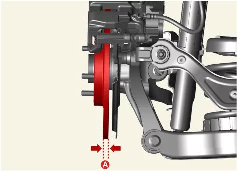
Measure the brake disc thickness (A) and run out using a micrometer and dial gauge. Measure it at least 24 points. Rear brake disc thickness (A) Standard : 10.0 mm (0.39 in.) Service limit : 8.4 mm (0.33 in.) DTV (Disc Thickness Variation : Less than 0.015 mm (0.0006 in.) [Circumference direction] Less than 0.015 mm (0.0006 in.) [Radial direction]
If the thickness difference between each measuring part is greater than standard, resurface or replace the brake disc.
Resurface the brake disc according to the method of using the equipment in possession.
If the brake disc is less than or equal to the limit, replace the brake disc with a new one.
Install the rear wheel and tires. (Refer to Suspension System - "Wheel")
Remove the rear wheel and tires. (Refer to Suspension System - "Wheel")
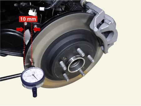
Install the dial gauge perpendicular to the brake disc's external diameter of 10 mm (0.40 in.) and rotate the disc to measure the run-out.
Brake Disc Run Out Service limit : 0.055 mm (0.002 in.) or less.
If the brake disc run-out exceeds the limit, resurface or replace the brake disc.
Resurface the brake disc according to the method of using the equipment in possession.
If the brake disc is less than or equal to the limit, replace the brake disc with a new one.
Install the rear wheel and tires. (Refer to Suspension System - "Wheel")
Release the parking brake. • EPB : Release the parking brake by using the KDS. (Refer to Brake System - "Electronic Parking Brake (EPB)") • None EPB : Release the hand lever parking brake fully.
Remove the rear wheel and tires. (Refer to Suspension System - "Wheel")
Disconnect the EPB actuator connector or parking brake cable. • EPB : Disconnect the EPB actuator connector (A). • None EPB : Remove the clip (A), and then separate the parking brake cable (B). [2WD] [4WD]
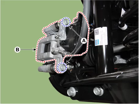
Remove the caliper body (B) after removing the guide rod bolt (A).
Tightening torque : 21.6 - 31 N·m
Secure the removed brake caliper body using a tool such as a cable tie.
Remove the brake pads (A).
Remove the caliper carrier (B) after removing the bolts (A).
Tightening torque : 98.1 - 118 N·m
Do not reuse the caliper carrier bolts.
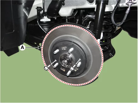
Remove the rear brake disc (A) after removing the screws.
Tightening torque : 4.9 - 5,9 N·m
Installation
Install in reverse order of removal.
Be careful not to interfere with the piston when assembling the caliper body to the carrier.
When installing the caliper body, turn the brake piston clockwise using a tool such as the long nose pliers (A) to press it in.
Check the piston groove position before installing the caliper body.
Fill the brake reservoir with brake fluid and perform air bleeding. (Refer to Brake System - "Brake Bleeding Procedures")
After installation, adjust the parking brake according to the parking brake specification.
EPB - (Refer to Parking Brake System - "Electronic Parking Brake (EPB)")
None EPB - (Refer to Parking Brake System - "Parking Brake Lever")
Depress the brake pedal several times to ensure that the brake pads are correctly positioned, then check operation.
Check the brake fluid leakage and pedal operating condition.
Check if the parking brake is operating normally.
Brake Pad Replacement
Special Service Tool
Tool Name / Number
Illustration
Description
Piston expander 09581 - 11000
Spreading the front brake caliper piston.
Replacement
Front brake pad
Remove the front wheel and tires. (Refer to Suspension System - "Wheel")
Remove the guide rod lower bolt (A) and then open the caliper body (B).
Tightening torque : 21.6 - 31 N·m
Remove the return springs (A).
Remove the brake pads (A).
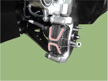
Remove the pad retainers (A).
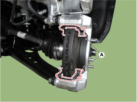
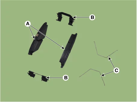
When replacing the brake pads, replace brake pads (A), retainers (B), and return springs (C) together.
Install in reverse order of removal.
Be careful not to damage the piston when pressing it.
Be careful not to touch the piston when installing the caliper body to the torque member.
Press the brake piston using SST (09581 - 11000) when installing the caliper body.
Depress the brake pedal several times to ensure that the brake pads are correctly positioned, then check operation.
Release the parking brake. • EPB : Release the parking brake by using the KDS. (Refer to Brake System - "Electronic Parking Brake (EPB)") • None EPB : Release the hand lever parking brake fully.
Remove the rear wheel and tires. (Refer to Suspension System - "Wheel")
Disconnect the EPB actuator connector or parking brake cable. • EPB : Disconnect the EPB actuator connector (A). • None EPB : Remove the clip (A), and then separate the parking brake cable (B). [2WD] [4WD]
Remove the caliper body (B) after removing the guide rod bolt (A).
Tightening torque : 21.6 - 31 N·m
Secure the removed brake caliper body using a tool such as a cable tie.
Remove the brake pads (A).
Remove the pad retainers (A).
[None EPB]
When replacing the brake pads, replace brake pads, retainers, and return springs together.
Do not reuse the pad return spring.
Do not deform the pad return spring for installation.
Deformation can cause brake degradation, drag, and noise.
[EPB]
When replacing the brake pads, replace brake pads, retainers, and return springs together.
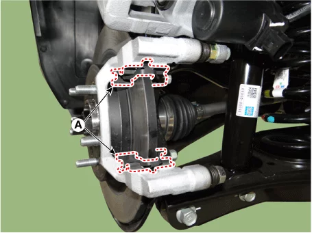
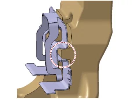
Ensure that there is no gap when installing the pad retainers.
Pad retainer gap can cause poor brake performance, drag, and noise.
Ensure that there is no deformation at the pad retainer retraction side.
Install in reverse order of removal.
Be careful not to interfere with the piston when assembling the caliper body to the carrier.
When installing the caliper body, turn the brake piston clockwise using a tool such as the long nose pliers (A) to press it in.
Check the piston groove position before installing the caliper body.
Depress the brake pedal several times to ensure that the brake pads are correctly positioned, then check operation.
Operate the parking brake several times to see if it works properly.
Release the parking brake using a KDS. [EPB] (Refer to Brake System - "Electronic Parking Brake (EPB)")
After disassembling/assembling the caliper body or replacing the brake pads, parking brake cable, and brake disc, the parking brake should be adjusted. [None EPB] (Refer to Brake System - "Parking Brake Lever")
Rear brake pad
Brake Pad Inspection
Inspection
Brake Pad Check
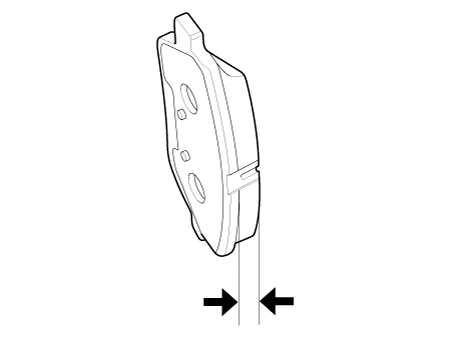
Check brake pad thickness. If the thickness is thinner than the limit, replace the brake pads. Front brake pad thickness for 15 inch wheel standard : 11.0 mm (0.43 in.) for 16 inch wheel : 11.5 mm (0.45 in.) Service Limit : 2.0 mm (0.078 in.) Rear brake pad thickness Standard (EPB) : 10.0 mm (0.39 in.) Standard (None EPB) : 9.0 mm (0.35 in.) Service Limit : 2.0 mm (0.078 in.)
Check that grease is applied to sliding contact points and check the pad and backing metal for damage.
Vacuum Pump - G 1.6 T-GDI GAMMA ll Removal and Installation
Removal
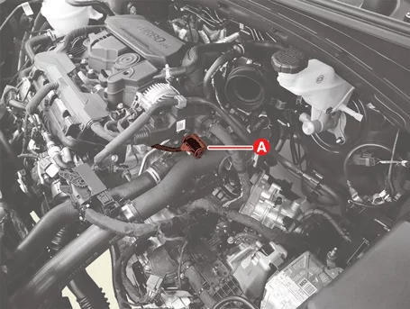
Remove the battery tray. (Refer to Engine Electrical System - "Battery")
Disconnect the wiring connector (A).
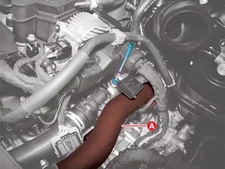
Remove the bolt and washer, and then separate the intercooler inlet pipe (A) to make a workspace.
Tightening torque : 18.6 - 24 N·m
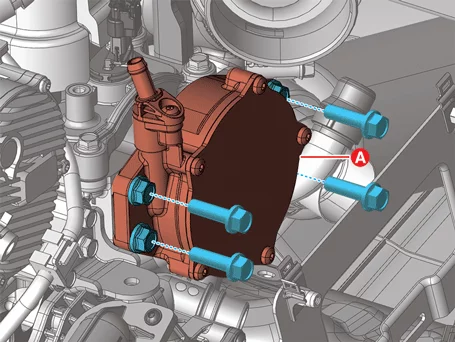
Remove the vacuum hose (A) from the vacuum pump.
Remove the bolts, and then remove the vacuum pump (A).









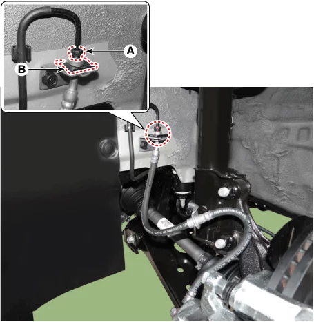
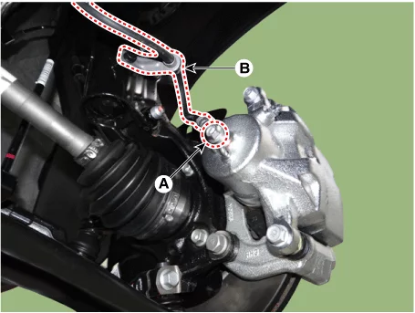
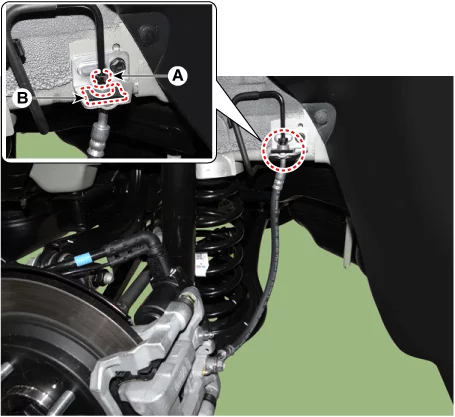
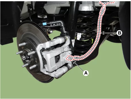
 A waveform inspection is performed using an oscilloscope on each part during vehicle acceleration/braking. (Refer to stop lamp switch circuit inspection procedures)
 Refer to the relevant repair procedures of the part when something abnormal is discovered in the waveform (Refer to the repair procedures of the relevant part and if necessary replace it)