Electric Vehicle Battery System
Battery Current Sensor Repair Procedures
In this manual: Electric Vehicle Battery System
11steps
~66min
3/5difficulty
Done 0 of 11
Inspection
- Turn the ignition off.
- Disconnect high voltage. (Refer to High Voltage Battery Management System - "High Voltage Disconnection Procedure")
- Remove the high-voltage battery pack assembly. (Refer to High-Voltage Battery System - Repair Procedures - Removal).
- Remove the high-voltage battery upper cover. (Refer to High-Voltage Battery System - Housing - "Upper Case")
- Connect the SST (No.: 0K918-E4100, 0K375-E4100, 0K375-E4200) to the vehicle as shown in the illustration below.
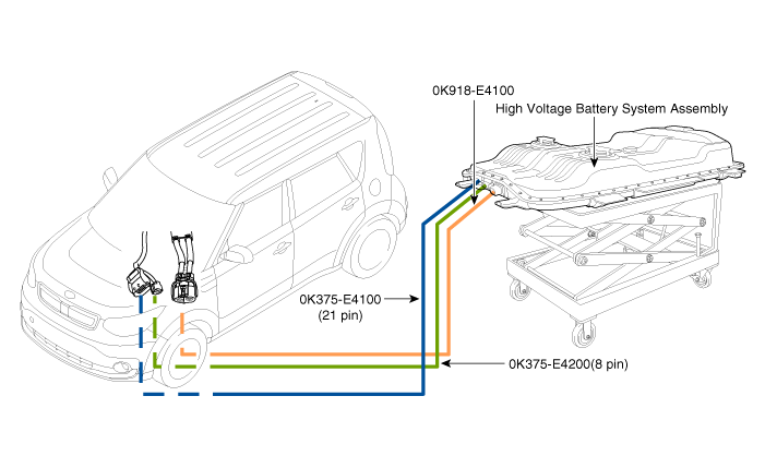
- Connect GDS to the DLC.
- Turn the ignition on.
- Check the "Battery Current" in the GDS data.
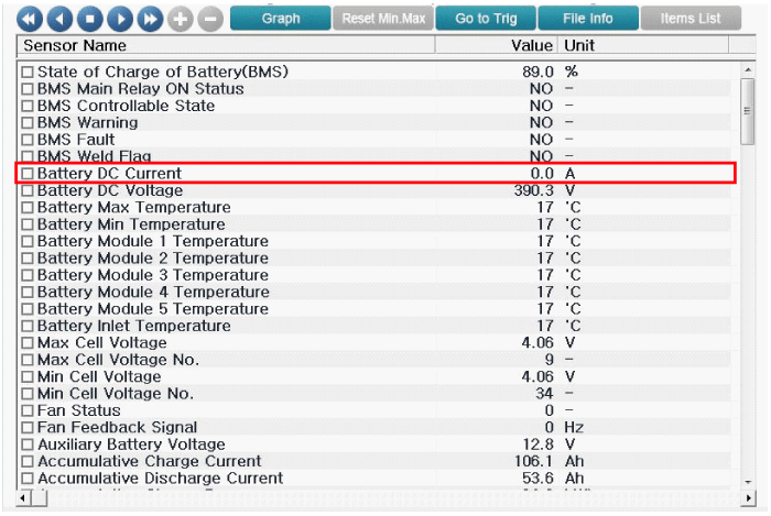
- Check the voltage for each current.
Current (A) Output voltage (V) -400 (Charging) 0,5 -200 (Charging) 1,5 0 2,5 200 (Discharging) 3,5 +400 (Discharging) 4,5 - Measure the voltage between terminal No. 12 (sensor output) and terminal No. 26 (sensor ground) of the BMS ECU connector E.
Specification: Approximately 2.5 V ± 0.1 V
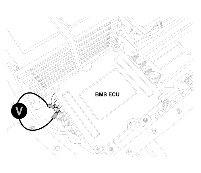
- Measure the voltage between terminal No. 1 (sensor power) and terminal No. 26 (sensor ground) of the BMS ECU connector E.
Specification: Approx. 5 V ± 0.1 V
Removal
|

Installation
|
Test yourself
A quick Kia Soul EV Owner's Manual quiz: every answer comes with an explanation and a link to the manual page.
Was this page helpful?