ESP Control Module
Components and Component Location
Components
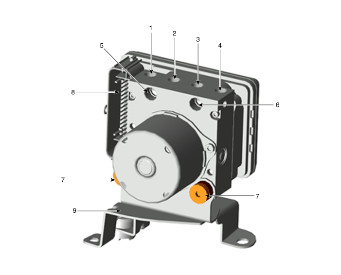
| 1. Front RH 2. Rear LH 3. Rear RH 4. FL 5. MC2 (PRI) |
6. MC1 (SEC) 7. Damper 8. ESP Control Module Connector 9. ESP Control Module Bracket |
Repair Procedures
Removal
[Left-hand drive]
Turn the ignition switch OFF and disconnect the negative (-) battery cable.
Separate the engine room relay block.
(Refer to Body Electrical System - "Engine Room Relay Block").
Disconnect the ESP connector.

Loosen the flare nuts of the ESP brake tube.
Tightening torque:
(A): 16,7–21 N·m
(B) : 20,6–24 N·m
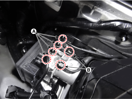
Loosen the ESP bracket bolts and remove the ESP.
Tightening torque: 16.7–26 N·m
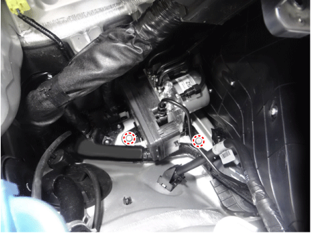
[Right-hand drive]
Turn the ignition switch OFF and disconnect the negative (-) battery cable.
Remove the air cleaner.
D 2.2 R VGT (Refer to Engine Mechanical System - "Air Cleaner")
D 2.2 R VGT (Enhanced Euro 6) (Refer to Engine Mechanical System - "Air Cleaner")
G 2.0 T-GDI (Refer to Engine Mechanical System - "Air Cleaner")
G 3.3 T-GDI (Refer to Engine Mechanical System - "Air Cleaner")
Recover the refrigerant.
(Refer to Heating, Ventilation and Air Conditioning - "Repair Procedures")
Disconnect the discharge line (A) and the suction line (B).
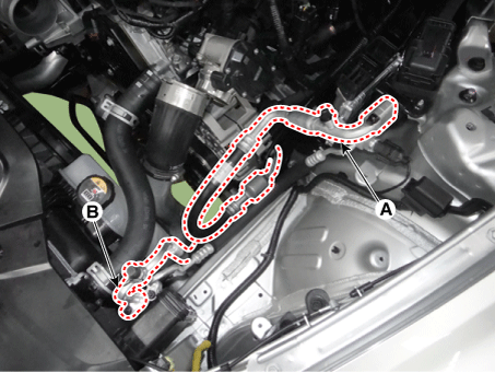
Remove the LH hood seal cover (A).
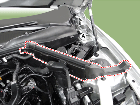
Disconnect the wiring connector and wire harness from the engine room.
Disconnect the ECM connector (A) and the TCM connector (B).
Remove the wiring protector (C).
Tightening torque:
5.9–8.8 N·m (0.6–0.9 kgf·m, 4.3–6.5 lbf·ft, 52.1–78.1 lbf·in)
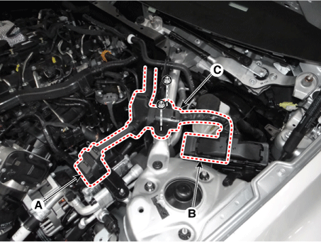
Remove the engine control module (ECM).
D 2.2 R VGT (Refer to Engine Control/Fuel System - "Engine Control Module (ECM)").
D 2.2 R VGT (Enhanced Euro 6) (Refer to Engine Control/Fuel System - "Engine Control Module (ECM)")
G 2.0 T-GDI (Refer to Engine Control/Fuel System - "Engine Control Module (ECM)").
G 3.3 T-GDI (Refer to Engine Control/Fuel System - "Engine Control Module (ECM)").
Remove the hood damper rod (A).
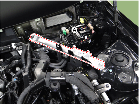
Remove the Transmission Control Module (TCM).
D 2.2 R VGT (Refer to Automatic Transmission System - "Transmission Control Module (TCM)")
D 2.2 R VGT (Enhanced Euro 6) (Refer to Automatic Transmission System - "Transmission Control Module (TCM)")
G 2.0 T-GDI (Refer to Automatic Transmission System - "Transmission Control Module (TCM)")
G 3.3 T-GDI (Refer to Automatic Transmission System - "Transmission Control Module (TCM)")
Loosen the suction and liquid tube mounting bolts (A).
Tightening torque: 8.8–13.7 N·m

Remove the suction and liquid tube assembly (A).

Remove the air duct (A).

Separate the relay block in the engine compartment (A).

Disconnect the ESP connector (A).

Loosen the flare nuts of the ESP brake tube.
Tightening torque:
(A): 16,7–21 N·m
(B) : 20,6–24 N·m
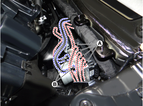
Remove the ESP control module (A).
Tightening torque: 16.7–26 N·m

Installation
Install in the reverse order of removal.
After installation, bleed the brake system.
(Refer to Brake System - "Brake Bleeding Procedures")
Diagnostic Procedure Using a Diagnostic Tool
Perform the diagnostic procedure using the diagnostic device as shown below:
Connect the self-diagnosis connector (16-pin) located under the driver's side instrument panel, then turn the ignition switch ON.
Select "Vehicle Model" and "ESP/ESC" on the KDS vehicle selection screen, then select OK.
[Variant Code Reset]


[Automatic Sensor Calibration]
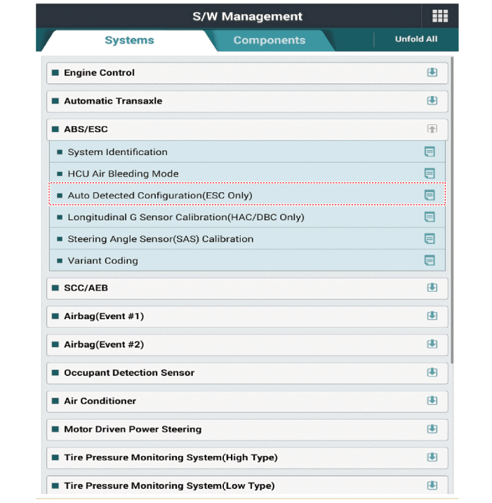
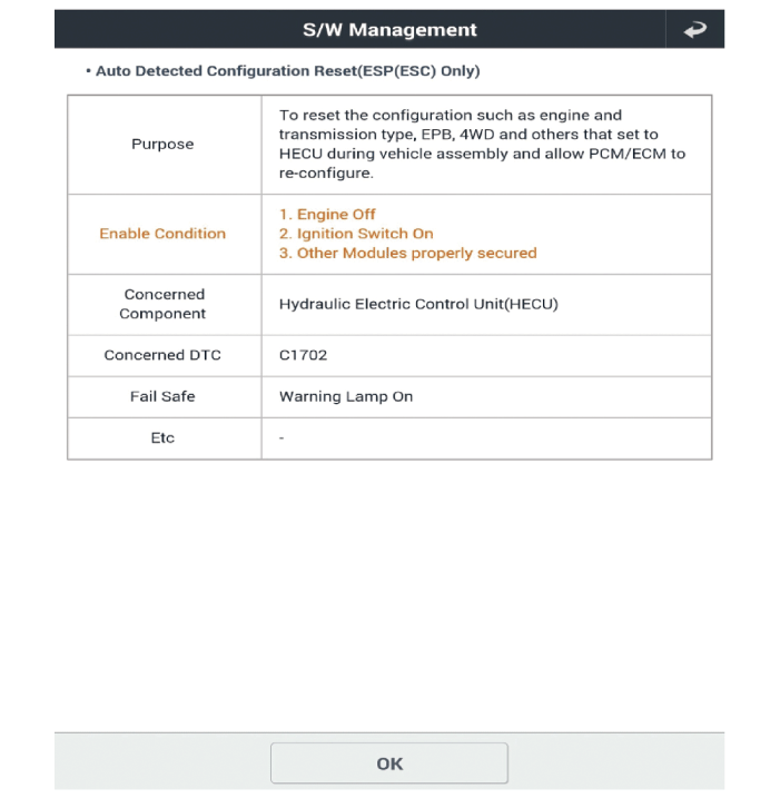
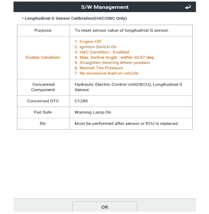
[Longitudinal Acceleration Sensor Calibration]

Test yourself
A quick Kia Stinger CK quiz: every answer comes with an explanation and a link to the manual page.