Instrument cluster
Components and Components Location
COMPONENTS LOCATION
[Default Type ("3.5")]
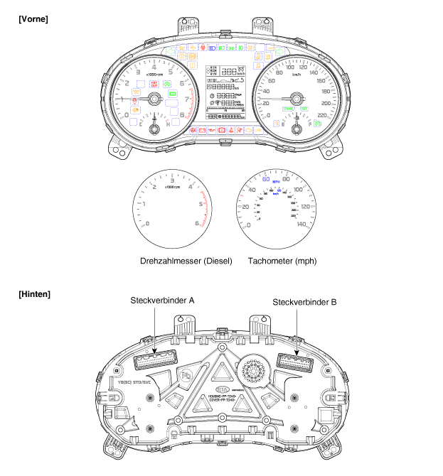
[Control Type ("3.5")]
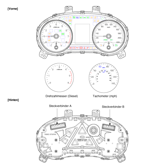
CONNECTOR PIN ASSIGNMENT
| CONNECTOR A |
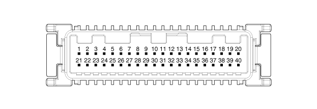 |
| No. | Description | No. | Description |
| 1 | Dimensions | 21 | Dimmer Switch (-) |
| 2 | Illumination Lamps (-) | 22 | Switch 1 (+) |
| 3 | Dimmer Switch Input (Down) | 23 | Switch 2 (+) |
| 4 | Dimmer Switch Input (Up) | 24 | Input Signal Active ECO Switch |
| 5 | Rest | 25 | Drive Mode Switch Input |
| 6 | Automatic Transmission ("P" Position) | 26 | MT ("R" position) |
| 7 | Automatic transmission ("R" position) | 27 | - |
| 8th | Automatic transmission ("N" position) | 28 | Low washer fluid_Input |
| 9 | Automatic transmission ("D" position) | 29 | Body CAN (Low) |
| 10 | Automatic transmission ("S" position) | 30 | Body CAN (High) |
| 11 | Immobilizer input | 31 | Alternator_Output |
| 12 | Vehicle speed sensor output | 32 | Chassis CAN [High] |
| 13 | Alternator input | 33 | Chassis CAN [Low] |
| 14 | Fuel tank sensor input (-) | 34 | Outside temp_Input |
| 15 | Vehicle speed input | 35 | FFV 5V(+)_Output LPI Fuel_Input |
| 16 | Fuel tank sensor input (-) | 36 | Steering wheel heater indicator input |
| 17 | Water separator (+)_Input | 37 | Dimensions |
| 18 | AIRBAG (+) _ Input | 38 | LDC battery (+)_Input |
| 19 | Oil Pressure Switch_Input | 39 | IGN1 |
| 20 | Rear lamp input signal | 40 | Battery (+) |
| PLUG B |
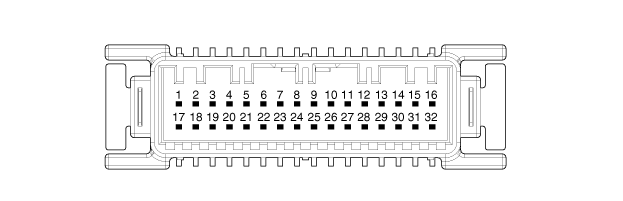 |
| No. | Description | No. | Description |
| 1 | Turn signal lamp (right)_Input | 17 | Parking brake switch (-)_Input |
| 2 | Turn signal lamp (left)_Input | 18 | Front wiper switch (-)_Input / Window heater switch (-)_Input |
| 3 | Headlamp (high beam) (+)_Input | 19 | Driver seat belt switch (-)_Input |
| 4 | Headlamp (low beam) (+)_Input | 20 | Auxiliary seat belt switch (-)_Input |
| 5 | Front fog lamp (+)_Input | 21 | Auxiliary seat cushion switch (-)_Input |
| 6 | Rear fog lamp (+)_Input | 22 | Sunroof switch (-)_Input |
| 7 | Rear fog lamp switch (-)_Input | 23 | Dimensions |
| 8th | Door open switch (-)_Input | 24 | Heated washer nozzle (-)_Output |
| 9 | Driver door open switch (-)_Input | 25 | Rear heater relay (-)_Output |
| 10 | Trunk open switch (-)_Input | 26 | Front divider relay (-)_Output / Window heater relay (-)_Output |
| 11 | Hood open switch (-)_Input | 27 | Auxiliary seat belt indicator (-)_Output |
| 12 | Key in switch (-)_Input | 28 | Tail lamp relay (-)_Output |
| 13 | Tail lamp switch (-)_Input | 29 | Rear SBR indicator SYNC (-)_Output |
| 14 | Rear window heater switch (-)_Input | 30 | - |
| 15 | Rear SBR buzzer (-)_Input | 31 | - |
| 16 | Brake fluid switch (-)_Input | 32 | - |
Schematic diagrams
Circuit diagram
[General purpose]
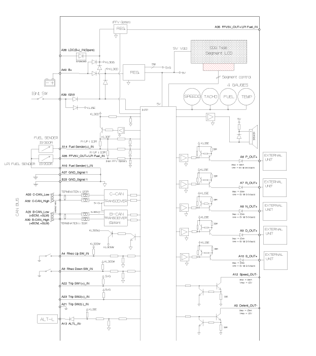
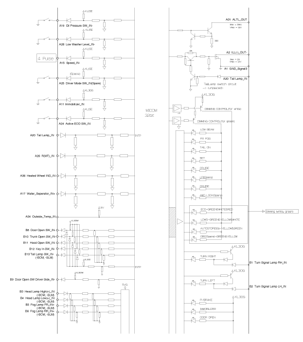
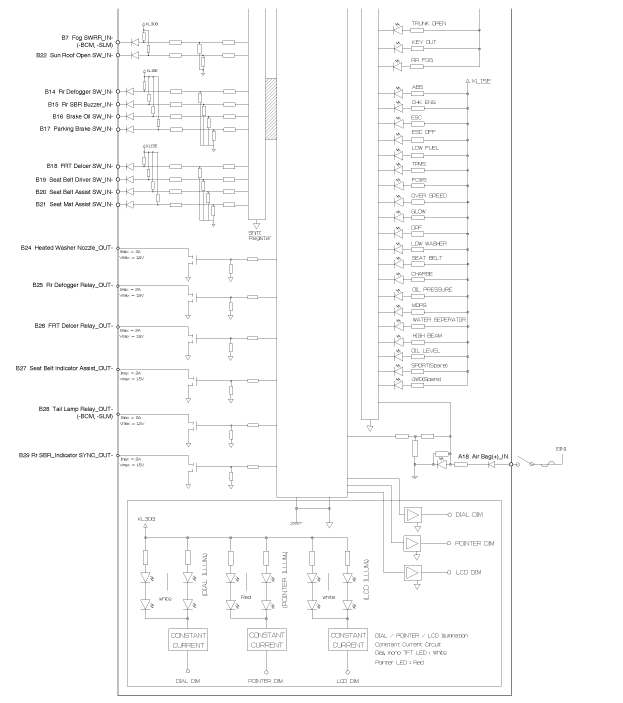
[General monitoring]
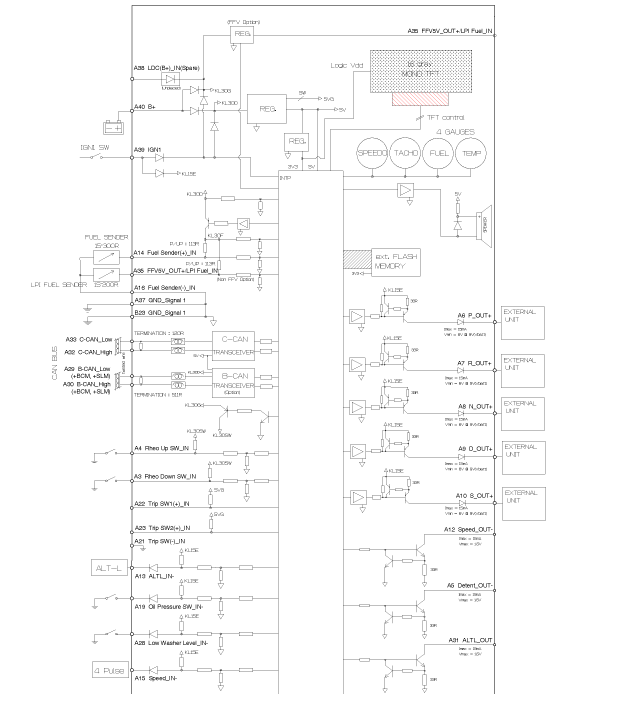
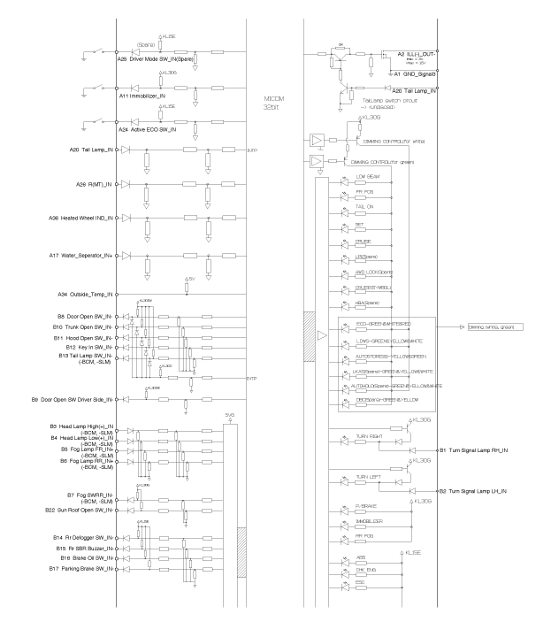
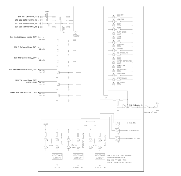
Description and Operation
Description
Communication Network Diagram
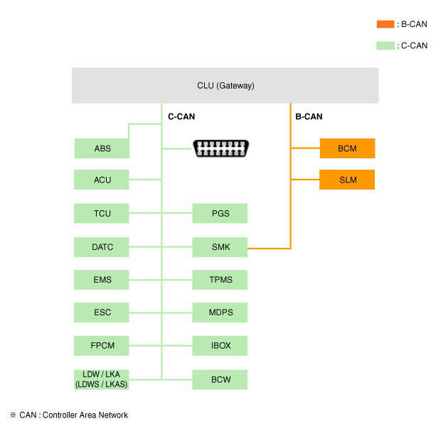
| ABBREVIATIONS | EXPLANATION |
| ACU | Airbag Control Unit |
| AVN | Main unit (audio/AVN) |
| B-CAN | Body CAN (controller area network) |
| BCM | Body Control Module |
| B.C.W | Blind-Spot Collision Warning |
| C-CAN | Chassis CAN (controller area network) |
| PDM | Instrument Cluster Module |
| ESC | Electronic Stability Program |
| Operating systems. | engine control system |
| FPCM | Fuel Pump Control Module |
| LDW | Lane Departure Warning |
| M_CAN | Multimedia controller network |
| MDPS | Motor-Driven Power Steering (MDPS) |
| MFS | combination switch |
| P_CAN | Powertrain CAN |
| PGS | Parking Assist System |
| CAC | Steering angle sensor |
| SMK | Smart Key |
| TCU | Transmission Control Unit |
| SCP | Tire Pressure Monitoring System |
| VDC | Vehicle Dynamic Control |
| SECTION | Anti-lock Brake System (ABS) |
Instrument cluster variant coding
Because the vehicle has more options (ESC, MDPS, etc.), the instrument panel provides additional displays for information on the selected options.
For this reason, when replacing the instrument panel, we must know which options the vehicle is equipped with.
When replacing the instrument panel, programming must be performed correctly with regard to which options are required for the applicable vehicle.
This is called variant coding.
repair procedures
expansion
Disconnect the battery ground cable.
Remove the instrument panel cover.
(Refer to Body — "Instrument Panel")
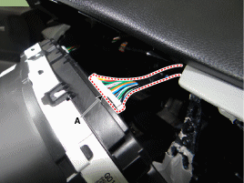
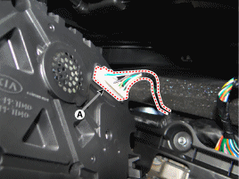
Loosen the mounting screws, then remove the combination meter (A).
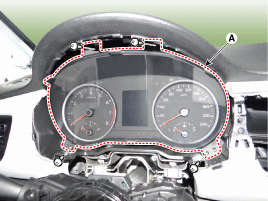
Disconnect the connector of the combination meter (A), then remove the combination meter.
Installation
After connecting the cluster connectors, install the cluster.
Install the instrument panel cover.
Connect the negative (-) battery terminal.
TEST
TPMS (warning lamp)
NO Link icon PURPOSE Color Signal input Signal control Checkpoint 1 
Left turn signal) GREEN CAN Gateway
(gateway)multifunction switch
BCM
CAN malfunction
2 
Right turn signal) GREEN CAN Gateway
(gateway)multifunction switch
BCM
CAN malfunction
3 
Tail lamp GREEN CAN Gateway
(gateway)multifunction switch
BCM
CAN malfunction
4 
FRONT
FOG LAMPSGREEN CAN Gateway
(gateway)multifunction switch
BCM
CAN malfunction
5 
Rear Fog Lamp YELLOW CAN Gateway
(gateway)multifunction switch
BCM
CAN malfunction
6 
DIMMED HEADLAMPS GREEN CAN Gateway
(gateway)multifunction switch
BCM
CAN malfunction
7 
High Beam Blue CAN Gateway
(gateway)multifunction switch
BCM
CAN malfunction
8th 
Home icon YELLOW CAN BSD BSD System
CAN malfunction
SCP TPMS system
CAN malfunction
BCM Exterior lighting
BCM
CAN malfunction
Hard Fuel Gauge Fuel tank sensor fault
Harness Malfunction
WIPE LOW Washer fluid level sensor
Harness Malfunction
DIGITAL INPUT Service Interval Warning 9 
Charge the battery. Red CAN ECM Charging System
CAN malfunction
10 
LPRINT Red Hard ECM ECM system
Hard
CAN malfunction
11 
Check Engine YELLOW CAN ECM ECM system
CAN malfunction
12 
Immobilizer YELLOW CAN Gateway
(gateway)SMK system
BCM
CAN malfunction
Hard
13 
Parking Brake
Brake Fluid
EBD
EPBRed CAN Billion Cubic Meters
(Gateway)
EBD
EPB
SECTION
TCSBCM
ABS SYSTEM
EPB system
CAN malfunction
Parking Brake Switch
Brake Fluid Level Sensor.
14 
SECTION YELLOW CAN SECTION ABS SYSTEM
CAN malfunction
15 
ESC YELLOW CAN TCS ABS SYSTEM
CAN malfunction
16 
OFF YELLOW CAN TCS ABS SYSTEM
CAN malfunction
17 
Auto Hold WHITE
YELLOW
GREENCAN TCS TCS System
CAN malfunction
18 
seat belt Red CAN Gateway
(gateway)BCM
CAN malfunction
19 
AIRBAG Red CAN SRSCM SRSCM system
CAN malfunction
20 
EPS
[MDPS]Red CAN MDPS MSPP Module
MDPS Motor
CAN malfunction
21 
SCP YELLOW CAN SCP TPMS system
TPMS Sensor
CAN malfunction
22 
LDW GREEN
YELLOW
WHITECAN LDW LDW System
CAN malfunction
23 
Fuel Warning Timer YELLOW Direct
(Micom)fuel segment Fuel tank sensor fault
Harness Malfunction
24 
Door Open Red CAN Gateway
(gateway)BCM
CAN malfunction
Door Sensor/Switch
25 
ECO GREEN Hard ECO Mode ECM system
CAN malfunction
26 
SPORT MODES YELLOW Hard sport mode ECM system
CAN malfunction
27 
CRUISE GREEN CAN ECM ECM system
CAN malfunction
28 
SET GREEN CAN ECM ECM system
CAN malfunction
29 
OVERSPEED YELLOW CAN ECM ECM
CAN malfunction
30 
AEB YELLOW CAN CCS AEB System
CAN malfunction
31 
Coolant
TemperatureRed CAN Operating systems. Emergency Medical Assistance System
CAN malfunction
32 
Diesel Particulate Filter
[DPF]YELLOW CAN ECM DPF system
CAN malfunction
33 
Oil Resistant YELLOW CAN ECM ECM
CAN malfunction
34 
Water Separator Red Hard Water Separator Sensor Water Separator Sensor
Harness Malfunction
35 

Auto Stop GREEN
YELLOWCAN ECM ECM
CAN malfunction
Checkpoint
NO PURPOSE Signal input Signal Control
(Module / Sensor)Checkpoint 1 SPEEDOMETER C-CAN ABS/ESC 1) ABS System
2. CAN Line Malfunction2 TACHOMETER C-CAN ECM 1. ECU
2. CAN Line Malfunction3 Engine Coolant Temperature C-CAN ECM 1. ECU
2. CAN Line Malfunction4 Fuel Hard Wire Fuel Gauge 1) Fuel Sensor Malfunction
2. Wiring Malfunction
Diagnosis Using KDS
Faulty body electrical components can be quickly identified using the vehicle diagnostic system (KDS).
The diagnostic system (KDS) provides the following data.
Self-diagnosis: check for malfunctions and diagnostic trouble codes (DTC).
Current data: check the status of system inputs/outputs.
Actuator test: check the operating status of the system.
Additional functions: control other functions, including system option settings and zero point adjustment.
Select "Vehicle Model" and "Cluster Module (CLU)" to select the vehicle. Check with the tester.
Select the "Current Data" menu to view the current status of the input/output data. Search.
Forcibly input the input value of the module under test; select the "Actuation Test" option.
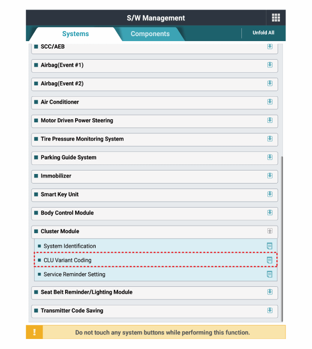
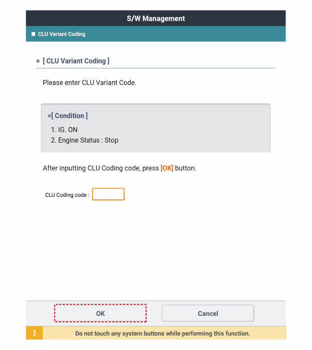
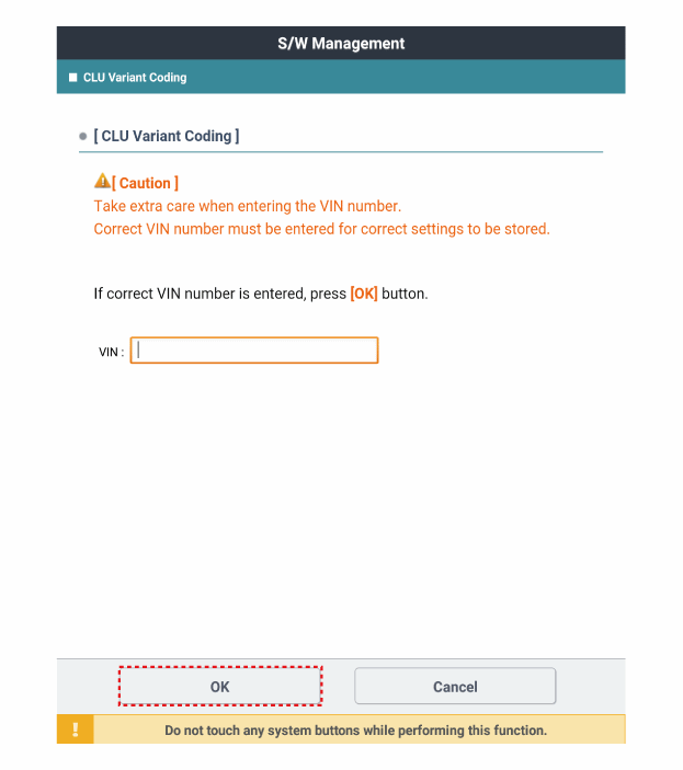
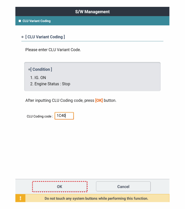
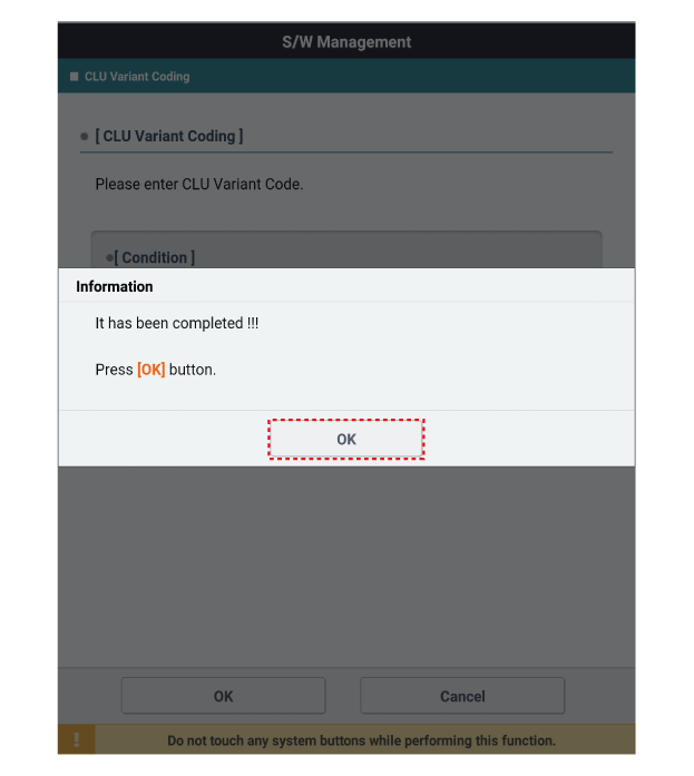
CLU Variant Coding
If a new instrument cluster is installed, perform "variant coding".
Connect the KDS to the diagnostic connector under the instrument panel cover on the driver's side and turn it on.
Select the model and "BCM".
Select the variant coding mode.
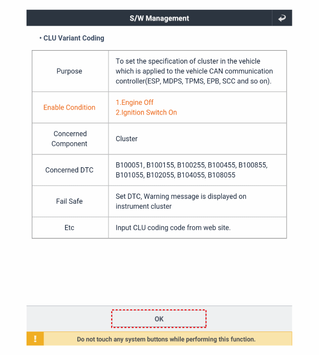
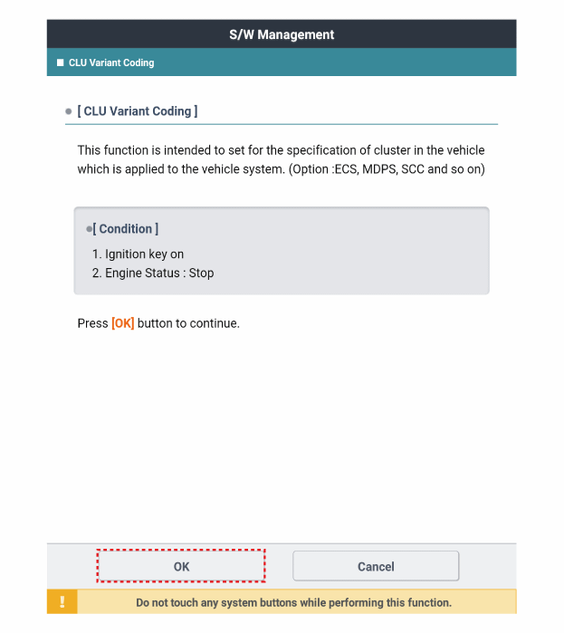
If trouble codes remain after performing variant coding, check the installation status of the instrument cluster, then perform variant coding again.
Test yourself
A quick Kia Stonic quiz: every answer comes with an explanation and a link to the manual page.