Blind-Spot Collision Warning (BCW)
Technical Data
Technical Data
| Component | SPECIFICATIONS |
| Nennspannung (Rated Voltage) | Gleichstrom 12 V |
| Betriebsspannung | 9 - 16 V |
| Betriebsgeschwindigkeit | 15 - 250 km/h |
| Erfassungsabstand | 30 m (Limousine) |
| Curve radius | Start: more than 100 m Stop: less than 70 m |
| Frequency | 24 GHz |
| Quantity | 2 stacks (1 leading, 1 trailing rod) |
Bauteile und bauteile-Übersicht
BAUTEILE-ÜBERSICHT
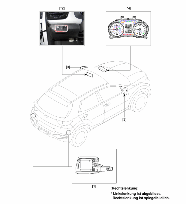
| 1. Blind Spot Collision Warning (BCW) Unit 2. Blind Spot Collision Warning (BCW) Switch |
3. Blind Spot Collision Warning (BCW) Warning Light 4. Instrument Cluster |
Beschreibung und bedienung
Beschreibung
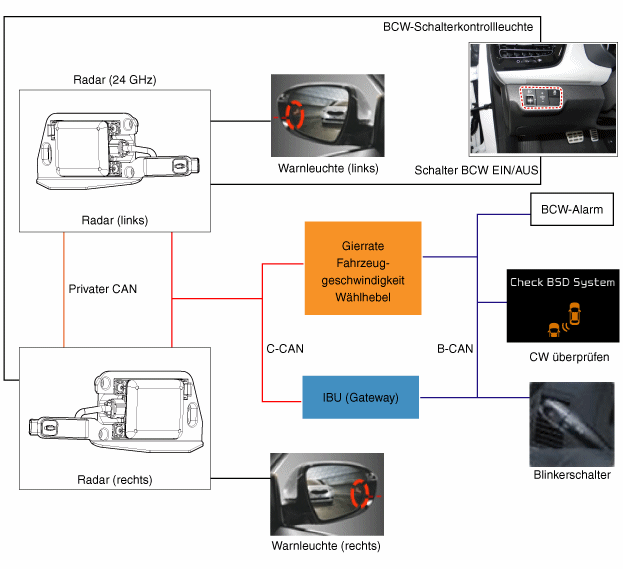
The BCW is a system that uses two microwave radar sensors mounted in the rear bumper to measure the distance to the following vehicle. In addition to detection, it issues a visual and audible alarm when a vehicle enters the blind spot.
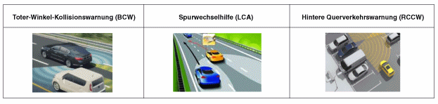
Blind Spot Collision Warning (BCW) System: Detects other vehicles in the rear blind spot area and warns the driver with a warning light in the outside rearview mirror.
Spurwechselhilfe(LCA)-System: Erfasst Fahrzeuge, die sich mit hoher Geschwindigkeit Seitlich Hinter dem Fahrzeug annahern und warnt den Fahrer.
System für Hintere Querverkehrswarnung (RCCW): Gibt beim Rückwärtsfahren Alarme für vonhinten und der Seite herannahende Fahrzeuge aus.
System-Betriebsmodus
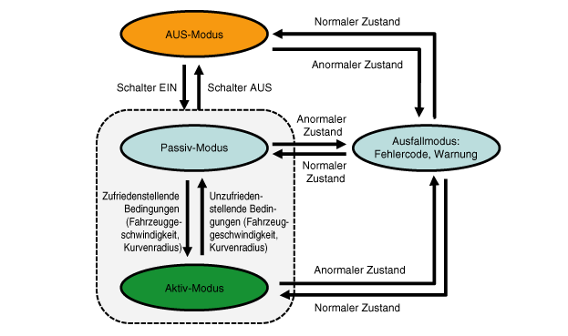
Wenn der Motor gestartet wird, während der Schalter auf aus steht, dann wird der AUS-Modus eingeschaltet.
Wenn im AUS-Modus der ON-Schalter gedrückt wird, dann wird der Passivmodus eingeschaltet.
Wenn der Motor gestartet wird, während der Schalter auf EIN steht, dann wird der Passivmodus eingeschaltet.
※ Wenn die Zündung eingeschaltet ist, dann befindet sich der Schalter im Anfangszustand: Die letzte Position wird beibehalten.
Wenn die Zündung aus- und dann eingeschaltet wird, während der Schalter auf EIN steht, dann steht der Schalter auf EIN.
Wenn die Zündung aus- und dann eingeschaltet wird, während der Schalter auf AUS steht, dann steht der Schalter auf AUS.
When the engine is started with the BCW switch on, or when the BCW is turned on while the BCW switch is off, the warning light in the door mirror flashes for 2 to 3 seconds.
This informs the driver that the BCW system is ready for operation (however, if the system is in fail-safe mode, the warning light does not flash).
When the activation conditions (vehicle speed and curve radius) are met while driving, the active mode is turned on (warnings are issued).
When the activation conditions (vehicle speed and curve radius) are not met while driving, the passive mode is turned on (warnings are not issued).
Wenn der Betrieb von BCW und LCA in irgendeinem Modus fehlschlägt, dann wird der Notlaufmodus eingeschaltet.
Wenn der Betrieb von BCW und LCA im Notlaufmodus normal funktioniert, dann wird der AUS-Modus eingeschaltet.
When the OFF switch is pressed while the BCW and LCA function is operating (active/passive), the OFF mode is turned on.
Warning
Warning Zone
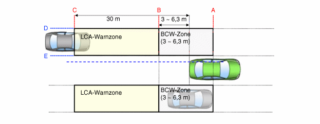
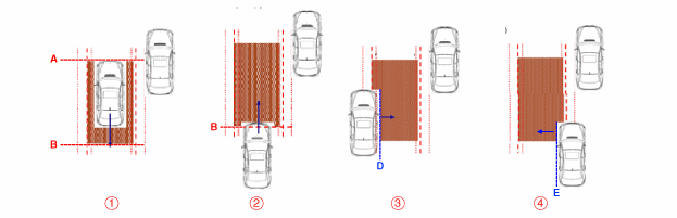
Bedingungen für das Einschalten der BCW-Warnung
① The entire body of the target vehicle is behind line A.
② Ein beliebiger Teil des Zielfahrzeugs überschreitet die Linie B.
③ Any part of the target vehicle crosses line D and the hysteresis line.
④ The entire part of the target vehicle crosses line E and the hysteresis line.
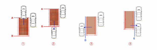
Bedingungen für das Ausschalten der BCW-Warnung
① The entire body of the target vehicle moves in front of line A.
② The entire body of the target vehicle moves behind line B.
③ The entire body of the target vehicle crosses line D and the hysteresis line.
④ The entire part of the target vehicle crosses line E and the hysteresis line.
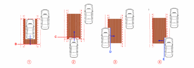
Bedingungen für das Einschalten der LCA-Warnung
① The entire body of the target vehicle is behind line B.
② Ein beliebiger Teil des Zielfahrzeugs überschreitet die Linie C.
③ Any part of the target vehicle crosses line D and the hysteresis line.
④ The entire part of the target vehicle crosses line E and the hysteresis line.
⑤ Under all the above conditions, the TTC (time to collision) is less than 3 seconds.
Bedingungen für das Ausschalten der LCA-Warnung
① The entire body of the target vehicle is in front of line B.
② Der gesamte Teil des Zielfahrzeugs überschreitet die Linie C.
③ The entire body of the target vehicle crosses line D and the hysteresis line.
④ The entire body of the target vehicle crosses line E and the hysteresis line.
⑤ TTC (time to collision) is more than 3 seconds.
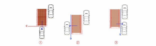
Sensor-Aktivierungsbedingungen
① BCW and LCA switch (indicated by switch LED) is turned on.
② Vehicle speed: 30 km/h or faster
③ Curve radius: min. 125 m
④ Relative vehicle speed: -10 to 250 km/h
(A negative value refers to overtaking the vehicle ahead.)
Sensor-Deaktivierungsbedingungen
① BCW and LCA switch (indicated by switch LED) is turned off.
② Vehicle speed: 27 km/h or slower
③ Curve radius: 125 m or less
④ Relative vehicle speed: all except -10 to 250 km/h
(A negative value refers to overtaking the vehicle ahead.)
Sperrung des Systembetriebs
① Das Radar ist von Schmutz beeckt: Systembedingungen - Blockademeldung wird ausgegeben
② Radareinbauzustand durch externen Stoß beeinträchtigt: Fehlercode wird gesendet
③ BCW and LCA system malfunction: fault code is output
System für Hintere Querverkehrswarnung (RCCW)
No. SPECIFICATIONS Bemerkungen Fahrzeuggeschwindigkeit 0 to -10 km/h R position Relative speed 4 - 60 km/h +: Approaching Betriebsbereich 0.5 - 20 m Passenger car: 20 m
Motorcycle: 15 m
① Diese Funktion unterstützt den Fahrer beim Zurücksetzen aus einer Parklücke, indem es Fahrzeuge erfasst, die sich vonhinten bzw. seitlich annahern und per Sicht nicht erkannt werden können.
② If the target vehicle is within 2 s based on the TTC (time to collision), a warning is output. Pedestrians are not considered obstacles for driver warnings (a warning may not be output).
③ Warning zone

Repair Procedures
Diagnosis using KDS
A BCW system defect detected during actuator test operation can be quickly identified by monitoring input/output values with the KDS and by self-diagnosis.
KDS-Kabel mit dem Diagnosesteckverbinder hinter der unteren Armaturenbrettverkleidung auf der Fahrerseite verbinden, dann das KDS einschalten.
Fahrzeugmodell und BCW-System wählen.
To check the current data of the BCW system, select "Input/Output Check".
To force the module check, select "Actuation Test".
Test yourself
A quick Kia Stonic quiz: every answer comes with an explanation and a link to the manual page.