Rear Corner Radar
Specifications
Specifications
| Item | Specification |
| Rated Voltage | 12 V |
| Operating Voltage | 9 - 16 V |
| Max. Distance | 70 m |
| Quantity | 2 units (Master unit 1, Slave unit 1) |
| Function | BCA, MOAB, RCCA |
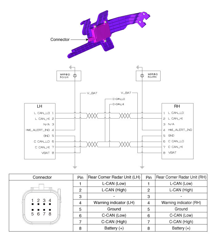
Circuit Diagrams
Connector and Terminal Function
Repair Procedures
Inspection
In the body electrical system, faults can be quickly diagnosed using the Korean Diagnostic System (KDS).
The Diagnostic System (KDS) provides the following information.
Self-diagnosis: check for malfunction and diagnostic trouble code (DTC).
Current Data: Check the system input/output status.
Operation check: Check the operating status of the system.
Special Function: Control of other functions, including parameter setting and zero point adjustment.
Removal
Disconnect the negative (-) battery terminal.
Remove the rear bumper assembly.
(Refer to Body - "Rear Bumper Assembly")
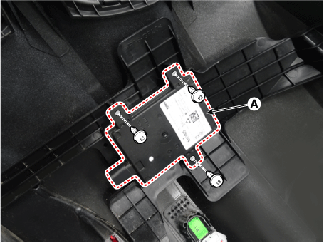
Disconnect the connector (A) from the rear corner radar unit.

Remove the rear corner radar (A) by loosening the screws.
Installation
Install in the reverse order of removal.
Adjustment
To correctly detect vehicles in adjacent lanes with the radar, the sensor direction and the vehicle traveling direction must be aligned.
This is the alignment of the rear corner radar unit. If this alignment is not performed as shown in the figure below, detection performance may decrease and false warnings may occur.
In particular, vehicles with a rear bumper damaged in an accident and vehicles with a replaced rear corner radar unit must perform this alignment procedure.

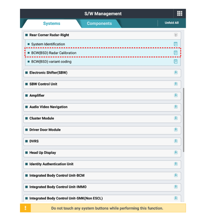
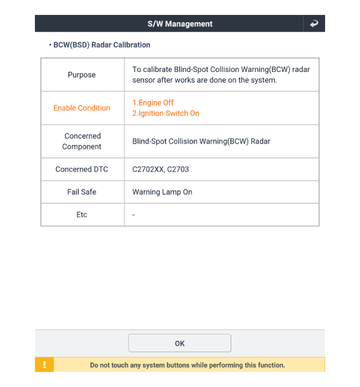
Perform the radar calibration procedure using the KDS.
Select the "BCW(BSD) Radar Calibration" procedure in the "Rear Corner Radar" system.
Perform the "BSD Radar Calibration" procedure as instructed on the KDS screen.
Test yourself
A quick Kia Optima DL3 quiz: every answer comes with an explanation and a link to the manual page.