Brake control
Tc and cg terminal circuit
In this manual: Brake control
12steps
~72min
3/5difficulty
Done 0 of 12
Description
Inspection procedure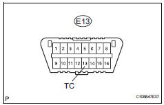






Replace abs and traction actuator assembly








Replace abs and traction actuator assembly
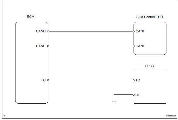
Connecting terminals tc and cg of the dlc3 causes the skid control ecu to display 2-digit dtcs by flashing the abs warning light.
Wiring diagramInspection procedure
- Check dlc3 (tc voltage)
- Turn the ignition switch on.
- Measure the voltage of the dlc3.
- Check can communication system
- Check the dtc (see page ca-34).
Replace abs and traction actuator assembly
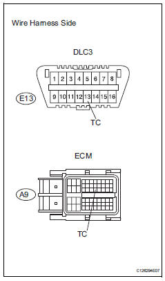
- Check wire harness (dlc3 - ecm and body ground)
- Turn the ignition switch off.
- Disconnect the a12 ecm connector.
- Measure the resistance of the wire harness side connectors.
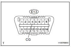
- Check wire harness (dlc3 - body ground)
- Measure the resistance of the dlc3.
- Check can communication system
- Check if the can communication dtc is output (see page ca-34).
Replace abs and traction actuator assembly
Test yourself
A quick Toyota RAV4 quiz: every answer comes with an explanation and a link to the manual page.
Was this page helpful?