Brake control
Control module communication bus off
In this manual: Brake control
16steps
~96min
4/5difficulty
Done 0 of 16
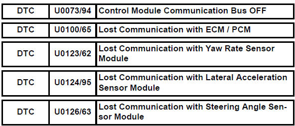
Description
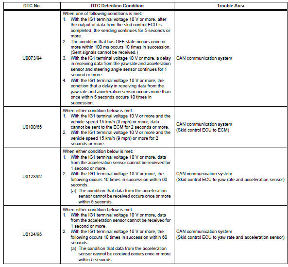

Inspection procedure
The skid control ecu inputs the signals from the ecm, steering angle sensor, and yaw rate and acceleration sensor via can communication system.
- Check harness and connector (momentary interruption)
- Using the data list of the intelligent tester, check for any momentary interruption in the wire harness and connector corresponding to a dtc (see page bc-23).
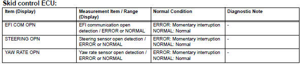
Result
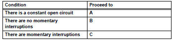
Hint:
Perform the above inspection before removing the sensor and connector.


- Check if each sensor and ecm connector is securely connected
- Check if each sensor or ecm connector is securely connected.


- Reconfirm dtc
- Record the output dtcs (for abs, vsc and can communication) (see page bc-47).
If the can communication system dtc and the relevant sensor dtcs are output simultaneously, troubleshoot the relevant sensor dtcs (for abs and vsc) after the can communication system returns to normal.
Result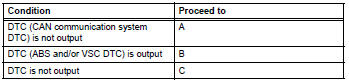

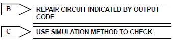
Inspect can communication system
- Repair or replace harness and connector
- Repair or replace the harness or connector.
- Check for any momentary interruption between the skid control ecu and each sensor or ecm (see page bc-23).
- Check that there is no momentary interruption.

- Reconfirm dtc
- Clear the dtc (see page bc-47).
- Turn the ignition switch on.
- Drive the vehicle and turn the steering wheel to the right and left at a speed of 15 km/h or more.
- Check that no can communication system dtc is output (see page bc-47).
- If abs and/or vsc dtcs are output, record them.
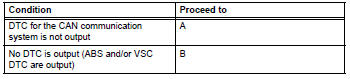

Hint:
The can communication system must be normal when repairing the sensor dtcs (for abs and vsc).

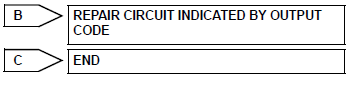
Inspect can communication system
Test yourself
A quick Toyota RAV4 quiz: every answer comes with an explanation and a link to the manual page.
Was this page helpful?