Crankshaft
PROCEDURE
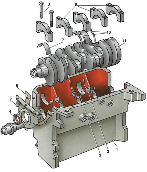
Crankshaft and Cylinder Block 1 – cylinder block; 2 – upper main bearing shell; 3 – upper thrust half-washer; 4 – front crankshaft oil seal; 5 – oil pump; 6 – oil pump gasket; 7 – lower main bearing shell; 8 – main bearing cap bolt; 9 – main bearing cap; 10 – lower thrust half-washer; 11 – crankshaft
Removal PROCEDURE 1. Disconnect the connecting rods from the crankshaft. If only the crankshaft is to be removed, the cylinder head and pistons with connecting rods do not need to be removed. 2. Remove the oil pump (see subsection 2.2.1.11).
3. Remove retainer 3 (see figure Cylinder Block and Crankcase) of the rear crankshaft oil seal (see subsection 2.2.1.9).
4. Measure the crankshaft axial clearance with a feeler gauge between the center main journal web and thrust half-washer 10 (see figure Crankshaft and Cylinder Block). It must be within 0.07–0.18 mm. Maximum permissible clearance is 0.20 mm. 5. Unscrew bolts 8 and remove main bearing caps 9 with shells 10, marking their position beforehand. Main bearing caps 9 are stamped with bearing numbers; cap No. 1 must be on the camshaft drive side. 6. Remove crankshaft 11, take out shells 2 from the main bearing seats and thrust half-washers 3, marking their position beforehand. Clean and wash all parts in gasoline. Inspection Inspect the crankshaft. The bearing surfaces must have no chips, nicks, scratches, or similar damage. Minor scratches can be ground and polished. Measure the main and connecting rod journals. If they are smaller than nominal dimensions (main journal 53.958–53.978 mm, connecting rod journal 41.955–41.970 mm), regrind them to a repair size. If the crankshaft has cracks, replace it. Check the out-of-round of the connecting rod journals with a micrometer. If the out-of-round exceeds 0.017 mm, regrind the journals to a repair size. Check crankshaft runout at the center main journal. Permissible runout is 0.03 mm; if runout is greater, replace the crankshaft. Measure the clearance between the main bearing shells and crankshaft journals. To do this, install the main bearing shells in place, lay the crankshaft on them. Place pieces of calibrated plastic wire "Plastigage" on the crankshaft journals, install the main bearing caps with their shells, and tighten to torque 65 N·m. Do not rotate the crankshaft. Remove the main bearing caps and determine the clearance from the flattened width of the wire using the scale on the packaging. Nominal clearance is 0.03–0.08 mm. Maximum permissible clearance is 0.17 mm. Measure the clearance between the connecting rod shells and crankshaft journals in the same way. Tighten the connecting rod cap nuts to torque 30 N·m. Nominal clearance is 0.03–0.076 mm. Maximum permissible clearance is 0.095 mm. Installation PROCEDURE 1. Install main bearing shells 2 in the seats so that the tab of the shell engages the recess in the seat and the oil feed hole in the shell aligns with the hole in the seat. Lubricate shells 2 generously with engine oil. 2. Install thrust half-washers 3. Lubricate them with engine oil. 3. Lubricate the crankshaft journals with engine oil and lay the crankshaft on the main bearing seats. 4. Install shells 7 and thrust half-washers 10 in main bearing caps 9 and lubricate with engine oil. 5. Install center main bearing cap 9, insert bolts 8, tighten, and torque to 65 N·m. Check that the crankshaft rotates freely. 6. Install and tighten the remaining bearing caps in order, working outward from the center bearing. After installing each cap, make sure the crankshaft rotates freely. 7. Check the crankshaft axial clearance.
Test yourself
A quick Volkswagen Golf quiz: every answer comes with an explanation and a link to the manual page.