Inspection, Check and Repair of Cylinder Head
PROCEDURE
After disassembly, wash all parts in gasoline. Clean the combustion chambers and valves of carbon deposits. Use a metal straightedge and feeler gauges to check whether the cylinder head mating surface to the block is distorted. Place the straightedge on edge on the head surface lengthwise, crosswise and diagonally at several locations, and measure the gap between the straightedge and the head surface with a feeler gauge. If the gap exceeds 0.1 mm, the head must be resurfaced.Measuring Cylinder Head Height

a) engines with displacement of 1.1 and 1.3 L;
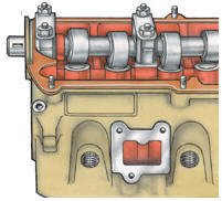
b) MH and 2G engines with displacement of 1.6 and 1.8 L
Minimum permissible cylinder head height: – for MH and 2G engines, between the upper and lower surfaces, 135.6 mm; – for other engines, between the lower edge of the camshaft seal bore and the lower surface, 119.3 mm. If the head height after resurfacing is less than specified, the head must be replaced. Check the side clearance between the valves and valve guides. To do this, insert the valve into the valve guide so that the end of the valve stem is flush with the top edge of the guide. Then, rocking the valve in the horizontal plane from stop to stop, measure the movement of the valve head with a dial indicator. This value shows the clearance. If the clearance exceeds 1 mm for intake valve guides or 1.3 mm for exhaust valve guides, the guides must be replaced. Before pressing out the old valve guide, measure how far it protrudes from the cylinder head so that the new guide can be installed to the same depth. Press out the guide using a mandrel. Before pressing in a new valve guide, heat the cylinder head to 70°C and lubricate the guide bore in the head and the new guide with engine oil.
Press in the new guide using a mandrel. Maximum permissible pressing force is 1 t. After pressing in the guide, check it and, if necessary, ream the valve guide bore.
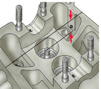
Measuring Dimension (a) between the valve stem end and the upper surface of the cylinder head
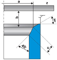
Valve Seat Dimensions a – outside diameter of the valve seat; b – distance from the cylinder head surface to the outside diameter of the seat; c – width of the valve seat contact face; z – lower surface of the cylinder head
NK engines: Intake valve, Exhaust valve: a = 32.2 mm, a = 26.5 mm; c = 2.0 mm, c = 2.4 mm; b = 2.55 mm, b = 2.85 mm. Other engines: Intake valve, Exhaust valve: a = 34.8 mm, a = 27.8 mm; c = 2.2 mm, c = 2.2 mm; b = 9.2 mm, b = 9.6 mm
Check the condition of the valve seats. There must be no signs of wear or burning. If necessary, the seats can be resurfaced. Grinding is performed on a special seat grinding machine or with a special grinder. On engines with hydraulic valve lifters, when grinding, maintain the minimum dimension "a" (see the figure Measuring the Distance between the Valve Stem End and the Upper Surface of the Cylinder Head). Dimension "a" for intake valves is 35.8 mm, and for exhaust valves 36.1 mm. If dimension "a" is less than specified, the hydraulic valve lifters will not operate correctly. Therefore, the reduction of the valve seat contact face must not exceed the difference between dimension "a" before grinding and the minimum permissible value of dimension "a". If the seats cannot be restored by grinding, they can be milled and the valves then lapped. Valve seat dimensions are shown in the figure Valve Seat Dimensions.
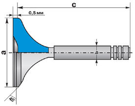
Valve Dimensions a – valve head diameter; b – stem diameter; c – valve length
NK engines: Intake valve, Exhaust valve: a = 34.0 mm, a = 28.1 mm; c = 7.97 mm, c = 7.95 mm; b = 110.5 mm, b = 110.5 mm. Other engines: Intake valve, Exhaust valve: a = 36.0 mm, a = 29.0 mm; c = 7.97 mm, c = 7.97 mm; b = 98.9 mm, b = 99.1 mm
Check the condition of the valves. If the valve seats show signs of wear or burning, lap the valves to the seats. If damage to the seat face is significant, the intake valve faces can be ground. Exhaust valve faces must not be ground; only lapping is permitted. If the exhaust valve seat face cannot be restored by lapping, replace the valve. If the valve face has deep scratches that cannot be removed by grinding or lapping, or if the valves are bent, burnt or cracked, replace the valves. When machining valves, maintain the specified dimensions (see figure Valve Dimensions). Lapping the valve to the seat PROCEDURE 1. Install the spring on the valve. 2. Apply lapping compound, a mixture of fine abrasive powder and engine oil, to the valve face. 3. Insert the valve with the spring into the cylinder head; the spring must press the valve away from the seat. 4. Attach a lapping tool to the valve stem or a rubber suction cup to the valve head. 5. Rotate the valve in both directions using the tool or suction cup, periodically pressing the valve lightly against the seat. 6. Do not remove too much metal from the valve face and seat during lapping, as this reduces the number of possible seat and valve refinishes and shortens their service life.
7. Towards the end of lapping, reduce the amount of abrasive powder. When the lapped surfaces are completely smooth and have an even grey colour, continue lapping with clean engine oil only.
8. An external sign of satisfactory lapping is a uniform matte grey colour of the valve face and seat. After lapping, wipe the seat and valve with a clean cloth. 9. To check the lapped valve for leaks, install it in the cylinder head together with the spring and keepers. Then lay the head on its side and pour kerosene into the port closed by the valve. If the kerosene does not leak into the combustion chamber within 10 minutes, the valve is considered sealed. Check the condition of the valve springs. Springs that are cracked or broken must be replaced. The spring height can be compared with that of a new spring.
If the spring removed from the engine is shorter than a new spring, replace it. Inspect the rocker arms. If there is wear at the point where the rocker arm contacts the camshaft lobe, replace the rocker arm. If a dent is visible on the contact surface between the rocker arm and the valve, grind the surface of the rocker arm. Inspect the camshaft. If the lobes and journals have deep scratches, wear or scoring, replace the camshaft. Install the camshaft in the cylinder head bearings and measure the side clearance between the camshaft and the ignition distributor mounting plate (on MH and 2G engines, between the camshaft and bearing cap No. 3). If the clearance exceeds 0.15 mm, replace the camshaft or the plate.
Measure the camshaft journal diameters, which must be: – front journal – 31.45 mm; – centre journal – 39.95 mm; – rear journal – 40.45 mm. Maximum permissible journal wear is 0.25 mm. The camshaft of MH and NU engines has a cast collar between the cams of cylinder 1. The journal diameter of the camshaft on MH and 2G engines (with hydraulic valve lifters) is 26.0 mm; minimum permissible journal size is 25.75 mm. If the measured diameter is less than the permissible value, replace the camshaft.
Check the camshaft runout by placing it on V-blocks, supported at the centre journal. Maximum permissible camshaft runout is 0.02 mm. If the runout exceeds this, replace the camshaft. Check and, if necessary, clean the oil passages in the camshaft journals. To check the cylinder head for cracks, connect a compressed air hose to one of the coolant jacket openings. Plug all other openings in the head with wooden plugs, immerse the head in a water bath and apply air. Air bubbles will escape from any cracks. Check the oil passages in the cylinder head in the same way.
Test yourself
A quick Volkswagen Golf quiz: every answer comes with an explanation and a link to the manual page.