Oil Pump
PROCEDURE
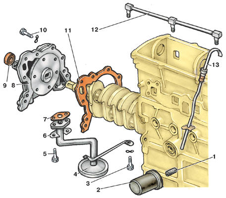
Engine Lubrication System Components 1 – filter fitting; 2 – full-flow oil filter; 3 – oil pump pickup mounting bolt to cylinder block; 4 – oil pump pickup; 5 – pickup-to-oil pump bolt; 6 – locking plate; 7 – pickup gasket; 8 – oil pump; 9 – front crankshaft oil seal; 10 – oil pump mounting bolt; 11 – oil pump gasket; 12 – oil line; 13 – oil level dipstick
Removal and Installation PROCEDURE 1. Remove the camshaft drive belt and crankshaft sprocket (see
subsection 2.2.1.7). 2. Remove the oil sump (see subsection 2.2.1.10).
3. Remove bolts 3 (see figure Engine Lubrication System Components) and 5 and remove oil pump strainer 4 with gasket 7 and plate 6. 4. Unscrew bolts 10 and remove oil pump 8 with gasket 11. 5. Remove pump cover mounting screws and remove cover. 6. Remove crankshaft front oil seal 9. 7. Clean pump components of dirt and wash in gasoline. If cover shows signs of wear, replace it. If gear teeth are worn or damaged, replace gears. Gears must be replaced as a pair only. Replace gaskets 7 and 11 and seal 9. 8. Assemble and install pump in reverse order. Before pressing in, lubricate seal with engine oil.
9. The outer pump gear has a triangular mark that must face the pump cover. 10. Tighten oil pump and strainer mounting bolts to torque 10 N·m. 11. Before assembling pump, lubricate all parts with engine oil. Removal, Inspection and Installation of Oil Pump, MH and 2G Engines
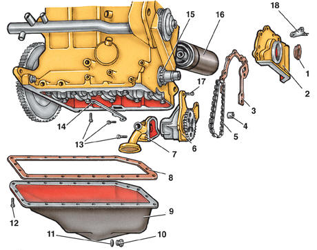
Lubrication System Components, MH and 2G Engines 1 – crankshaft front oil seal; 2 – oil pump drive cover; 3 – cover gasket; 4 – bushing; 5 – chain; 6 – oil pump; 7 – oil pump strainer; 8 – oil pan gasket; 9 – oil pan; 10 – drain plug; 11 – plug gasket; 12 – oil pan bolt; 13 – oil pump strainer bolt; 14 – strainer bracket; 15 – oil pump drive sprocket; 16 – full-flow oil filter; 17 – oil pump mounting bolt; 18 – plate with ignition timing mark
PROCEDURE 1. Remove camshaft drive belt and crankshaft gear (see
subsection 2.2.1.7).
2. Remove oil pan (see subsection 2.2.1.10).
3. Remove cover bolts and remove cover 2 (see figure Lubrication System Components, MH and 2G Engines) and gasket 3. 4. Remove bracket 14 bolt from cylinder block. 5. Remove oil pump mounting bolts 17. 6. Remove chain 5 from crankshaft sprocket 15 and remove pump 6 with strainer 7 and chain 5. 7. Remove chain 5 from oil pump drive sprocket.
8. Unscrew pump cover bolts and remove cover with strainer 7.
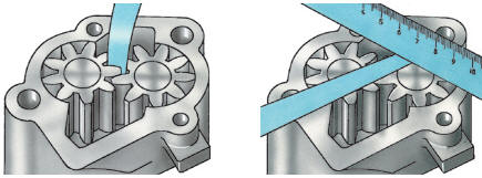
9. Measure gear tooth clearance with feeler gauge as shown in illustration on left. Clearance for new gears is 0.05 mm, maximum permissible 0.2 mm. Measure clearance between gear and pump housing with feeler gauge; it must not exceed 0.15 mm. Measure gear axial clearance as shown in illustration on right. It must not exceed 0.15 mm.
10. Unscrew relief valve from pump cover. 11. After disassembly, wash all pump parts in gasoline. 12. Assemble and install pump in reverse order. Replace crankshaft seal 1, lubricating it with engine oil beforehand.
13. A threaded plug is installed on the inside of cover 2. Inspect it and replace if necessary. 14. Before assembling pump, lubricate all parts with engine oil. 15. When installing pump, place chain 5 on pump sprocket and crankshaft sprocket 15. Install pump bolts 17 and tighten to torque 20 N·m.
Check chain 5 tension: hold pump sprocket and press chain with finger midway between sprockets. Chain should deflect 1.5–2.5 mm; otherwise loosen bolts 17 and tension chain by moving pump. Tighten bolts 17 to torque 20 N·m. 16. Replace gasket 3. 17. Tighten drive cover bolts to torque 10 N·m. 18. After pump installation, check lubrication system pressure. To do this, remove oil pressure sensor and install pressure gauge in its place. Oil pressure at crankshaft speed 2000 min-1 must be 20 bar.
Test yourself
A quick Volkswagen Golf quiz: every answer comes with an explanation and a link to the manual page.