Cylinder Head Disassembly
PROCEDURE
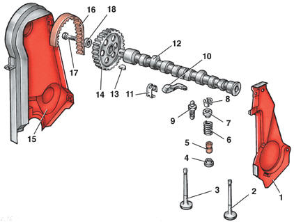
Camshaft and Valves 1 – camshaft drive rear cover; 2 – exhaust valve; 3 – intake valve; 4 – valve spring seat washer; 5 – valve stem seal; 6 – valve spring; 7 – valve spring retainer; 8 – valve keepers; 9 – rocker arm adjusting bolt; 10 – rocker arm; 11 – rocker arm spring; 12 – camshaft; 13 – woodruff key; 14 – camshaft gear; 15 – camshaft drive upper cover; 16 – camshaft drive belt; 17 – gear retaining bolt; 18 – washer
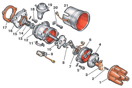
Ignition Distributor 1 – distributor cap; 2 – contact point with spring; 3 – rotor; 4 – dust shield; 5 – bolt; 6 – cover; 7 – movable contact; 8 – fixed contact; 9 – condenser; 10 – movable plate; 11 – distributor cap retaining spring; 12 – distributor housing; 13 – washer; 14 – spring; 15 – O-ring; 16 – distributor retaining plate; 17 – gasket; 18 – plate retaining bolt; 19 – vacuum advance unit; 20 – distributor retaining bolt; 21 – shield
PROCEDURE 1. Remove the fuel pump together with its gaskets. 2. Remove bolt 17 (see figure Camshaft and Valves). 3. Remove gear 14 and take the woodruff key 13 out of the camshaft groove. 4. Remove bolts 20 (see figure Ignition Distributor) and remove the ignition distributor. Remove washer 13, spring 14 and O-ring 15. 5. Remove bolts 18 and remove plate 16 and gasket 17. 6. Fully unscrew bolts 9 (see figure Camshaft and Valves) and remove springs 11 and rocker arms 10 from them, marking them so they can be reinstalled in their original positions.
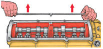
7. Remove the oil line. 8. Carefully, without damaging the journals and lobes, remove the camshaft toward the ignition distributor mounting side. 9. If necessary, remove oil seal 3 (see figure Cylinder Head). 10. Using a special tool, compress valve spring 6 (see figure
camshaft and valves) and remove the valve cotters. 11. Relieve the pressure on the tool lever to release the valve spring. Remove the tool. Remove retainer 7 and take out spring 6. 12. Remove valve stem seal 5 and spring seat washer 4. Place something in the combustion chamber beforehand to prevent the valve from falling out. 13. Remove the valve from the combustion chamber side and mark it so it can be installed in the same location during assembly. Remove the remaining valves in the same way. Disassembly of the cylinder head on MH and 2G engines (with hydraulic valve lifters)
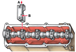
Bearing cap numbers on MH and 2G engines A – projection of the bearing cap facing the intake manifold; B – bearing number stamped on the cap
PROCEDURE 1. Remove the fuel pump with gaskets. 2. Remove the ignition distributor and camshaft gear as described in the previous section. 3. Unscrew the nuts and remove camshaft bearing caps No. 5, 1 and 3.
4. Loosen and evenly unscrew the nuts of bearing caps No. 2 and 4 in a diagonal sequence. Remove the caps. 5. Remove the camshaft and the seal. 6. Remove the hydraulic valve lifters. Mark them beforehand so they can be installed in their original positions. 7. Remove the valves as described above in steps 10–13.
Test yourself
A quick Volkswagen Golf quiz: every answer comes with an explanation and a link to the manual page.