Connecting Rod and Piston Assembly
PROCEDURE

Crankshaft and Connecting Rod and Piston Components 1 – crankshaft; 2 – connecting rod bearing shell; 3 – connecting rod cap bolt; 4 – piston pin; 5 – oil control ring; 6 – compression ring; 7 – piston; 8 – circlip; 9 – connecting rod small end bushing; 10 – connecting rod; 11 – connecting rod cap
Removal and Disassembly PROCEDURE 1. Remove cylinder head, oil pan and oil pump.
2. Mark each connecting rod and cap with its cylinder number. 3. Turn crankshaft so piston of cylinder 1 is at BDC. 4. Unscrew nuts and remove connecting rod cap 11 (see figure Crankshaft and Connecting Rod and Piston Components). Remove bearing shell 2 from cap 11, noting its position in the cap. 5. Remove piston with connecting rod from cylinder. Remove remaining pistons with connecting rods in the same way. 6. Remove bearing shells 2 from lower connecting rod ends, marking their positions. 7. Remove circlips 8 and, heating piston in hot water (about 60 °C), push out pins 4 with a mandrel. 8. Remove rings 5 and 6 from pistons using a piston ring expander. Inspection, Check and Repair of Connecting Rod and Piston Components
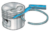
Measuring Piston Ring Side Clearance
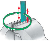
Filing Piston Ring Ends
After disassembly, clean all connecting rod and piston assembly parts and wash them in gasoline. Inspect the pistons. If they show signs of wear, deep scratches, or burning, replace the pistons. Using a micrometer, measure the piston skirt diameter at 10 mm from the bottom edge of the skirt, perpendicular to the piston pin axis. If the measured diameter differs from the nominal diameter by 0.04 mm, replace the piston. Measure the side clearance between the piston rings and the ring grooves in the piston, as shown in the figure. Measuring piston ring side clearance. If the clearance exceeds 0.15 mm, replace the rings or the pistons. Measure the piston ring end gap. To do this, insert the ring into the cylinder from the crankcase side and push it down with the piston, used as a press, to a distance of 15 mm from the bottom of the cylinder. Measure the end gap with a feeler gauge. If the gap exceeds 1.0 mm, replace the ring. If the end gap is less than 0.3 mm for compression rings or 0.25 mm for oil control rings, the ring ends can be filed with a file clamped in a vise, as shown in the figure. Filing piston ring ends. Check the fit of the piston pin in the connecting rod. To do this, set the connecting rod horizontally and insert the pin into the small end. The pin must not protrude from the small end under its own weight. If the pin protrudes or falls out, replace the pin and the small end bushing. Press out the old bushing and press in a new one into the connecting rod small end. Then drill an oil feed hole in the bushing to align with the oil hole in the small end. Next, ream the bore to the size of the new pin, maintaining an installation clearance of 0.004–0.01 mm. The connecting rod must rotate freely on the pin. Otherwise, press the pin through the bushing, and carefully hone the bushing at the places where marks from the pin remain. Then check again that the connecting rod rotates freely on the pin. Check the alignment of the upper and lower connecting rod bores on a surface plate and straighten the connecting rod if necessary.
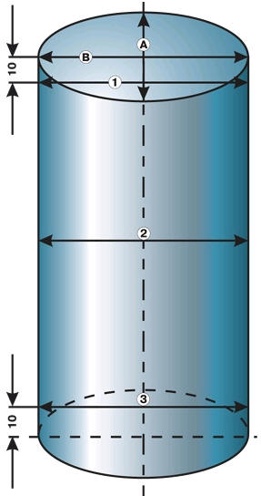
Cylinder bore measurement diagram A, B – measurement directions; 1, 2, 3 – measurement zones
Check the piston-to-cylinder clearance. If it exceeds 0.12 mm, bore and hone the cylinders to the next repair size. All four cylinders must be bored, even if the clearance exceeds the specification in only one of them. After boring, install oversize pistons in the cylinders. Piston-to-cylinder clearance is calculated as the difference between the cylinder bore diameter and the piston diameter. Measuring the piston diameter is described above in this same paragraph. Measure the cylinder bore with a bore gauge at six points: 10 mm from the bottom edge of the cylinder, 10 mm from the top edge, and in the middle, in two perpendicular directions, as shown in the figure. Cylinder bore measurement diagram. If cylinder wear from the nominal size exceeds 0.04 mm, the cylinders must also be bored to the repair size. Assembly
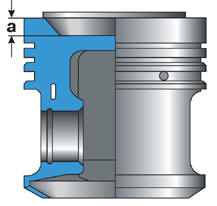
Piston head recess dimensions a = 16.1 mm; a = 56.6 mm – engine with fuel injection; a = 14.7 mm; a = 16.6 mm; a = 16.5 mm; b = 55.7 mm – model HZ; b = 56.6 mm – model MH, 2G, NU; b = 56.6 mm – model HK

Mark on piston crown and projections on connecting rod and connecting rod cap

Installing piston into cylinder 1 – ring compressor strap; 2 – hammer handle; 3 – piston
Pistons for different engine models differ in the size of the recess in the piston crown. Recess dimensions are shown in the figure. Piston head recess dimensions. In addition, on engines built from September 1985, the cylinder bore openings in the head gasket were reduced. The piston crown has a chamfer to prevent the piston from striking the edge of the gasket. Replace the connecting rod bolts before assembly. PROCEDURE 1. Heat piston 7 (see figure Crankshaft and connecting rod and piston assembly) by immersing it in water at 60° C for several minutes. 2. Insert connecting rod 10 into the hot piston so that the arrow on the piston crown and the projections on the connecting rod and rod cap, shown by arrows in the figure Mark on piston crown and projections on connecting rod and rod cap, point in the same direction. Insert pin 4 using a drift.
3. Install circlips 8 in place. Check that the piston rotates freely on the connecting rod. 4. Using a piston ring expander, install rings 5 and 6 on the piston. Before installing new rings, measure the end gap of each ring (see above). The letters "TOP" are engraved on the rings. Install the rings with the "TOP" mark facing the piston crown. Space the ring end gaps evenly at 120° to each other. 5. Turn the crankshaft so that the crank throw of cylinder 1 is at the bottom. 6. Lubricate the pistons and piston rings with engine oil. Place short pieces of rubber hose over the connecting rod bolts to avoid accidentally damaging the cylinder bore. 7. Place strap 1 (see figure Installing piston into cylinder) over the piston rings and compress them. Insert the connecting rod with the piston into the cylinder and, tapping lightly with handle 2 of a hammer, push the piston into the cylinder. Strap 1 must be pressed against the block, otherwise the piston rings may break.
8. Insert the pistons with connecting rods into the cylinders so that the arrow on the piston crown and the projections on the connecting rod and rod cap, shown in the figure Mark on piston crown and projections on connecting rod and rod cap, point toward the camshaft drive belt.
After the piston is installed in the cylinder, do not rotate it. 9. Remove the pieces of rubber hose from the connecting rod bolts. 10. Install bearing shell 2 in the lower connecting rod end according to the marks made during removal (see figure Crankshaft and Piston-Connecting Rod Assembly), so that the locating tab of the shell engages the recess in the connecting rod end. Lubricate the bearing shell generously with engine oil. Push the piston down so that the lower connecting rod end seats on the crankshaft crankpin journal. 11. Install bearing shell 2 in connecting rod cap 11 according to the marks made during removal. The locating tab of the shell must engage the recess in the cap. Lubricate the bearing shells generously with engine oil. 12. Install the connecting rod cap on the connecting rod bolts according to the marks made during removal. The boss on the cap, the mark on the piston crown, and the bosses on the connecting rod and cap must face the timing belt side, the same as on the connecting rod. 13. Lubricate the contact surfaces of the cap nuts with engine oil, install the connecting rod bolt nuts, and tighten them evenly in two stages: – Stage 1 – torque to 30 N·m; – Stage 2 – tighten an additional quarter turn (90°). 14. Turn the crankshaft to make sure it rotates freely. 15. Measure the connecting rod axial clearance between the lower connecting rod end and the crankshaft web with a feeler gauge. It must be within 0.05–0.31 mm. Maximum permissible clearance is 0.37 mm. 16. Install the remaining pistons with connecting rods in the same way.
Test yourself
A quick Volkswagen Golf quiz: every answer comes with an explanation and a link to the manual page.