2EE Ecotronic Carburetor Adjustment
PROCEDURE
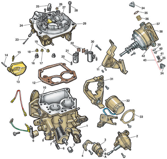
2EE Carburetor Components 1 – second chamber throttle lever; 2 – second chamber throttle diaphragm actuator (pneumatic); 3 – throttle valve potentiometer; 4 – bracket; 5 – connecting bushing; 6 – mixture quality (richness) adjustment screw; 7 – O-ring; 8 – first chamber throttle stop screw; 9 – heating element; 10 – carburetor body; 11 – bracket; 12 – gasket; 13 – float; 14 – float pin; 15 – needle valve; 16 – threaded plug; 17 – first chamber main jet; 18 – idle jet; 19 – second chamber main jet; 20 – wedge; 21 – first chamber venturi (diffuser); 22 – gasket; 23 – filter; 24 – choke valve; 25 – float chamber vent tube; 26 – flame arrester; 27 – full-load enrichment tube; 28 – cover retaining bolt; 29 – carburetor cover; 30 – second chamber venturi (diffuser); 31 – bracket; 32 – choke valve actuator; 33 – actuator retaining ring; 34 – plug; 35 – O-ring; 36 – filter; 37 – first chamber throttle actuator; 38 – vent valve; 39 – valve; 40 – valve seat; 41 – spring; 42 – air valve; 43 – check valve; A, B, C – potentiometer terminals
The 2EE carburetor is a 2E2 carburetor with electronic control. The choke valve actuator and the first chamber throttle actuator are controlled by a microprocessor-based electronic control unit. The control unit is installed in the passenger compartment near the glove box on the instrument panel. The lambda sensor, installed in the auxiliary muffler, measures the oxygen content in the exhaust gases and sends a signal to the control unit. Based on the lambda sensor signal, the control unit changes the composition of the combustible mixture so that the exhaust gases are optimally afterburned in the catalytic converter. The following operations are performed in the same way as on the 2E2 carburetor: – removal and installation of the carburetor; – adjustment of the second chamber throttle valve partial opening (see subsection 3.1.12.5); – checking the intake pipe heater (see subsection 3.1.12.5); – checking the intake pipe heater thermal switch (see subsection 3.1.12.5). Checking Idle Speed. The 2EE carburetor has no mixture quantity adjustment screw. PROCEDURE 1. Warm up the engine until the oil temperature is at least +60° C. 2. Switch off the engine and turn off all electrical consumers (headlights, fan, radio, etc.). 3. Disconnect the crankcase ventilation hose. 4. Connect a diagnostic tachometer. 5. Start the engine and let it run at idle. 6. Check the idle speed; it should be 750 rpm. If the idle speed differs from the specified value, determine the fault using the diagnostic system and correct it. Checking and Adjusting Carbon Monoxide Content in Exhaust Gases. The carbon monoxide (CO) content in the exhaust gases is checked with the VAG 1527 special LED voltage indicator. The CO content in the exhaust gases is determined by the pattern of the LED light pulses. Do not use conventional test lamps, as electronic systems may be damaged. The check is performed on a warm engine with an oil temperature of 60° C in the following sequence: PROCEDURE 1. Connect the exhaust gas analyzer to the special CO measuring port on the first stage auxiliary muffler. 2. Disconnect the crankcase ventilation hose.
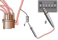
3. Connect the VAG 1527 voltage indicator to test connector 1 on the blue wire. 4. Start the engine and raise the speed above 2000 rpm within 1 min so that the lambda sensor warms up to operating temperature. 5. At idle speed, the LED on the voltage indicator 2 should flash at 1.5 times per second (2 times in 3 s). If the LED is constantly on, the mixture is too rich; if the LED is off, the mixture is too lean. If the LED flashes at 25 times per second, the lambda sensor has not reached operating temperature, is faulty, or the wire to the lambda sensor is damaged. Warning: The lambda sensor may become clogged with soot, which can cause incorrect sensor operation. To clean the sensor, drive smoothly on a highway for 20 min, then repeat the check. 6. Check the CO level using the exhaust gas analyzer. It should be 0.6%. If the CO level differs from the specified value, even though the voltage indicator LED readings are correct, it must be adjusted. To do this, disconnect the wire from the lambda sensor and insulate the lambda sensor connector with insulating tape. The voltage indicator LED should flash in this case. Remove the plastic cap from screw 6 (see figure Components of 2EE Carburetor) by drilling a hole in the cap, screwing a self-tapping screw into it, and pulling out the cap with it. Turning screw 6, adjust the CO content in the exhaust gases. 7. Install a new cap, disconnect the exhaust gas analyzer and the voltage indicator. Connect the wire to the lambda sensor. Connect the crankcase ventilation hose. Simplified Ecotronic System Check. If the lambda sensor fails, the Ecotronic system operates in emergency mode. To check operation in emergency mode, disconnect the lambda sensor and observe the opening and closing of the choke valve. If the valve operates, emergency control is functioning. PROCEDURE 1. Warm up the engine until the oil temperature is at least 60° C. 2. Remove the air filter. 3. Disconnect vacuum hose 24 from the carburetor (see figure Air Filter for 1.1 and 1.3 L Engines). Plug the carburetor port. 4. Start the engine and let it run at idle.

5. Disconnect the lambda sensor wire 1 from connector 2. The air flap should open to an angle of approximately 60°. If it does not, the emergency control or the air flap actuator is faulty, or the lambda sensor wire is shorted to ground. 6. If the air flap opened correctly, connect the green wire of connector 2 to ground for approximately 2 s. The air flap should slowly open slightly. If it does not, check the wiring for damage and, if the wiring is undamaged, replace the control unit with microprocessor. 7. Increase engine speed to 2000 rpm for approximately 1 min to warm the lambda sensor to operating temperature. 8. Connect lambda sensor wire 1 to connector 2. 9. With the engine idling, remove the plug from the carburetor port. The air flap should slowly close slightly. If it does not, the lambda sensor is faulty and must be replaced. If the lambda sensor is clogged with soot, drive on a highway for 20 min and then repeat the check. 10. Stop the engine. Connect hose 24 (see fig. Air cleaner, 1.1 and 1.3 L liter engines) to the carburetor port and install the air cleaner. Checking Ecotronic system components
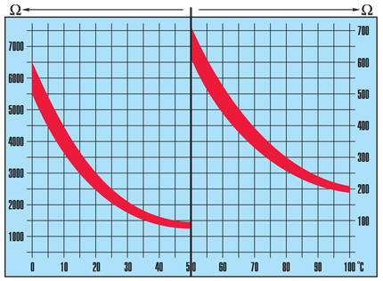
Coolant temperature sensor resistance vs. temperature graph
Checking the coolant temperature sensor. The coolant temperature sensor is installed in the engine intake manifold or in the cooling jacket outlet pipe. The sensor signal is sent to the control unit. If the sensor fails, engine starting in low ambient temperatures deteriorates. PROCEDURE 1. Disconnect the wire from the temperature sensor. 2. Measure the sensor resistance. At a temperature of +20 °C it must be 2000–3000 Ohm. 3. Connect the wire to the sensor, start the engine and warm it up. 4. Stop the engine and measure the sensor resistance again. At a temperature of +90 °C it must be 200–300 Ohm. Otherwise, replace the sensor. 5. The sensor can be checked by removing it from the engine and placing it in a container of water. Gradually heat the water and measure the sensor resistance. The relationship between resistance and sensor temperature is shown in the figure. Checking the air flap actuator PROCEDURE 1. Warm up the engine; oil temperature must be at least +60 °C. 2. Stop the engine. 3. Remove the air cleaner. 4. Check that the air flap closes and opens freely. 5. Start the engine and let it idle. 6. Quickly turn the throttle lever of the first chamber several times by approximately 1/3 of the travel between idle and full open position, then return the lever to idle. The air flap should quickly turn toward the closed position and return to its initial position. 7. If the air flap does not change position, check the resistance of the air flap actuator. To do this, disconnect the wiring connector from air flap actuator 32 (see fig. Carburetor components 2EE). Using an ohmmeter, measure the resistance between the air flap actuator terminals; it must be 0.9–1.7 Ohm. Then check the resistance between each terminal and ground (short to body); the ohmmeter must show infinity. 8. Stop the engine. Connect the wiring connector to the air flap actuator. Install the filter. Checking the throttle potentiometer Potentiometer 3 (see fig. Carburetor components 2EE) sends the throttle position signal of the first chamber to the control unit, as well as the signal of the throttle opening and closing speed. PROCEDURE 1. Disconnect the wiring connector from potentiometer 3. 2. Measure the resistance of the potentiometer between outer terminals A and C; it must be 1.4–1.6 kOhm. 3. Start the engine and let it idle. Disconnect the hose from actuator 37 to the air cleaner, detach it from the filter and plug it. 4. Stop the engine. The throttle valve must be fully closed. 5. Measure the resistance between terminals A and B; it must be 1.4–2.4 kOhm. Slowly open the throttle fully; the resistance must decrease smoothly. With the throttle fully open, the resistance must be less than 270 Ohm. 6. Reconnect the hose to the air cleaner. Connect the wiring connector to the potentiometer.
Test yourself
A quick Volkswagen Golf quiz: every answer comes with an explanation and a link to the manual page.