Pierburg/ Solex 2E2 Carburetor Adjustment
PROCEDURE

Pierburg/ Solex 2E2 Carburetor Components 1 – second-stage throttle valve actuator; 2 – throttle cable bracket; 3 – carburetor body; 4 – heating element; 5 – first-stage throttle valve thermostat; 6 – accelerator pump; 7 – accelerator pump cover; 8 – diaphragm; 9 – spring; 10 – valve seat; 11 – valve; 12 – power enrichment valve; 13 – first-stage throttle valve actuator; 14 – idle speed control valve; 15 – bracket; 16 – solenoid valve; 17 – vacuum valve with thermal timer; 18 – gasket; 19 – float; 20 – needle valve; 21 – filter; 22 – float axle; 23 – carburetor cover; 24 – mixture quality adjusting screw; 25 – fuel jet body; 26 – idle fuel jet; 27 – choke air valve actuator; 28 – choke air valve starting clearance adjusting screw; 29 – automatic choke device; 30 – cover; 31 – O-ring; 32 – choke device cover; 33 – housing; 34 – diaphragm stroke adjusting screw; 35 – second-stage main fuel jet; 36 – first-stage main fuel jet; 37 – accelerator pump nozzle; A, B, C – actuator ports
Engine Starting Idle Speed Adjustment Adjustment is performed on a warmed-up engine with correctly set ignition timing and adjusted idle speed, in the following sequence: PROCEDURE 1. Remove the air cleaner and disconnect vacuum hose 24 (see fig. Air Cleaner for 1.1 and 1.3 L Engines). 2. Connect a diagnostic tachometer to the engine. 3. Disconnect hose 2 from tee 1 (see fig. First-Stage Throttle Valve Actuator) and plug it. 4. Start the engine and check engine speed on the tachometer; it must be within 3000±200 rpm. 5. If engine speed differs from the specified value, adjust it with screw 1 (see fig. First-Stage Throttle Opening Adjustment). After adjustment, lock screw 1 with paint. Choke Air Valve Starting Clearance Adjustment

Location of Jets on 2E2 Carburetor Cover 1 – idle fuel jet; 2 – first-stage air jet; 3 – second-stage air jet; А – choke air valve starting clearance
PROCEDURE 1. Remove covers 30 (see fig. Pierburg/ Solex 2E2 Carburetor Components) and 32 from the automatic choke device. 2. Turn the choke air valve control lever in the automatic choke housing clockwise and secure it in this position with a rubber band. 3. Connect a vacuum gauge and vacuum pump to choke air valve actuator 27. 4. Create a vacuum of 100 mbar in the actuator. If the actuator is airtight, the vacuum must not drop by more than 5 mbar per minute and must not decrease below 40 mbar. 5. Increase the vacuum in the actuator to 200–300 mbar. 6. Measure the first-stage starting clearance “A” (see fig. Location of Jets on 2E2 Carburetor Cover) of the vacuum valve, between the lower edge of the air valve and the throat. It must be 2.5±0.15 mm for engines with displacement 1.6 L with manual transmission, 1.9±0.15 mm for automatic transmission, and 2.3±0.15 mm for engines 1.8 L. 7. If necessary, adjust the clearance with screw 34 (see fig. Pierburg/ Solex 2E2 Carburetor Components) at the end of the actuator cover. 8. Close the actuator atmospheric port 27 with a plug and create a vacuum of 200 mbar in it. The vacuum must not change within 1 min if the actuator is airtight. 9. Measure the second-stage starting clearance “A” (see fig. Location of Jets on 2E2 Carburetor Cover) of the choke air valve. It must be 5.0±0.15 mm for engines with displacement 1.6 L with manual transmission, 5.3±0.15 mm with automatic transmission, and 4.7±0.15 mm for engines with displacement 1.8 L.
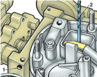
10. If the clearance differs from the specified value, insert a screwdriver into hole 1 and turn adjusting screw 2 to adjust the clearance. After adjustment, lock screw 2 with paint. When installing cover 30 (see fig. Pierburg/ Solex 2E2 Carburetor Components), the marks on the cover and housing 33 must align. First-Stage Throttle Valve Actuator Inspection
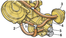
First-Stage Throttle Valve Actuator 1 – tee; 2 – vacuum hose; 3 – vacuum valve with thermal timer; 4 – first-stage throttle valve actuator; 5 – idle speed control valve; 6 – idle speed increase control valve (only for vehicles with air conditioning or automatic transmission, produced before January 1984)
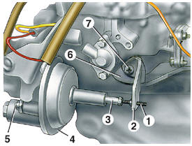
First-Stage Throttle Opening Adjustment 1 – throttle stop screw; 2 – throttle lever; 3 – actuator movable rod; 4 – first-stage throttle valve actuator; 5 – actuator rod adjusting screw; 6 – accelerator pump drive cam; 7 – locking screw
Vacuum actuator 13 (see figure Pierburg/Solex 2E2 Carburetor Components) may have three ports A, B and C for connecting vacuum hoses, or four. The vacuum actuator with four ports is installed on vehicles with air conditioning or automatic transmission produced before December 1984. PROCEDURE 1. Disconnect vacuum hoses from vacuum actuator 13. 2. Plug ports B and C. 3. Connect vacuum pump to port A. 4. Create vacuum in the vacuum actuator. Rod 3 (see figure Primary Throttle Valve Opening Adjustment) of the vacuum actuator must move. Rod protrusion from the edge of the guide bushing must be 8.5 mm. If this does not occur, the vacuum actuator is faulty and must be replaced. 5. On a vacuum actuator with four ports, remove the plug from port C (see figure Pierburg/Solex 2E2 Carburetor Components), then increase the vacuum in the vacuum actuator. The rod must extend 1 mm from the edge of the guide bushing, and rod position must not change for 1 min. Otherwise, replace the vacuum actuator. Secondary Throttle Valve Opening Adjustment: The throttle valve position is set at the factory and does not require adjustment during operation. If the adjustment has been disturbed, it can be restored in the same way as for the 2E3 carburetor (see subsection 3.1.12.4). Choke Vacuum Actuator Check: Perform the check in the same way as for the 2E3 carburetor (see subsection 3.1.12.4). Heating Element Check: Perform the check in the same way as for the 31P1C-7 carburetor (see subsection 3.1.12.2). Accelerator Pump Adjustment PROCEDURE 1. Remove the carburetor. 2. Disconnect vacuum hoses from vacuum actuator 13 (see figure Pierburg/Solex 2E2 Carburetor Components) of the primary throttle valve. 3. Connect vacuum pump to port A. Plug port B (on a four-port actuator, also plug port C). 4. Create vacuum in the vacuum actuator so that rod 3 (see figure Primary Throttle Valve Opening Adjustment) moves away from adjusting screw 1.
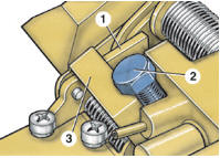
5. Turn lever 1 and secure it by inserting bolt 2 M8x20 between lever 3 and the carburetor body. 6. Remove the carburetor cover, fill the float chamber with fuel, and install the carburetor cover. 7. Place a graduated measuring cylinder with a funnel under the carburetor. 8. Turn the primary throttle valve from stop to stop 10 times, actuating the accelerator pump, taking about 3 s for each stroke. 9. Measure the fuel quantity in the measuring cylinder and divide by 10. This gives the fuel quantity delivered by the pump per cycle. This value must be 1.0±0.15 cm3 for engines with displacement 1.6 L, and 1.1±0.15 cm3 for engines with displacement 1.8 L. 10. If necessary, adjust the accelerator pump output by turning cam 6 (see figure Primary Throttle Valve Opening Adjustment), after first loosening locking screw 7. Idle Speed Adjustment: Adjust on a warm engine with valve clearances set and ignition timing correctly set, with the air choke fully open, as follows: PROCEDURE 1. Switch off all electrical consumers (headlights, fan, radio, etc.). 2. Disconnect the crankcase ventilation hose from the air cleaner and plug it. 3. Connect a tachometer and an exhaust gas analyzer. 4. Check that rod 3 (see figure Primary Throttle Valve Opening Adjustment) is in the idle position and screw 1 touches rod 3. 5. Turn valve 5 (see figure Primary Throttle Valve Vacuum Actuator) to adjust idle speed within 950±50 min-1.
6. Use mixture adjusting screw 24 (see figure Pierburg/Solex 2E2 Carburetor Components) to set the carbon monoxide (CO) content in the exhaust gas to 1.0±0.5%. Check and adjust idle speed if necessary. Check and adjust the CO content in the exhaust gas if necessary. Idle Speed-Up Valve Adjustment: On vehicles equipped with automatic transmission (produced before December 1984) or air conditioning, there is vacuum actuator 4 (see figure Primary Throttle Valve Vacuum Actuator) with four ports for connecting vacuum hoses, and idle speed-up valve 6. When many electrical consumers are switched on (headlights, radio, rear window defroster, etc.), or when driving modes change or air conditioning is switched on, the idle speed drops due to the heavy load. In this case, valve 6 opens and supplies additional fuel, which raises the idle speed to the nominal value. The idle speed-up valve is adjusted if the idle speed under load is too low or if the engine stalls.
Adjustment must be performed on a warm engine, with the valve train clearances adjusted and the ignition timing correctly set, with the throttle fully open, in the following sequence: PROCEDURE 1. Connect a test tachometer and exhaust gas analyzer. 2. Apply the parking brake and place wheel chocks (e.g., wooden wedges) under the front wheels. 3. Start the engine. Turn the heater fan to maximum, switch on the high beams and the rear window defogger. 4. The assistant seated in the vehicle must press the brake pedal fully and move the transmission selector lever to “D”. 5. Check whether the stop screw 1 (see fig. Throttle Opening Adjustment, Primary Barrel) contacts rod 3. Check engine speed with the test tachometer. If it is below 800 rpm (see fig. Throttle Actuator, Primary Barrel), adjust it by turning valve 6. 6. Disconnect vacuum hose 2 from tee 1 and plug it. Start the engine and check the fast idle speed. If it is below 3000±200 rpm, adjust it with screw 1 (see fig. Throttle Opening Adjustment, Primary Barrel). After adjustment, lock screw 1 with paint. 7. Connect vacuum hose 2 (see fig. Throttle Actuator, Primary Barrel) to tee 1. Check the idle speed. Intake Manifold Heater Check
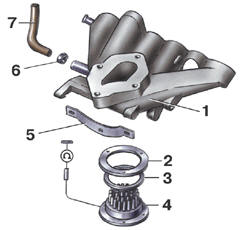
Intake Manifold Heater 1 – intake manifold; 2 – gasket; 3 – O-ring; 4 – heater; 5 – bracket; 6 – clamp; 7 – intake manifold heater hose
To improve fuel evaporation during starting when the engine is cold, an electric heater is installed on the underside of the intake manifold. It heats up within a few seconds and switches off when the coolant temperature reaches 65° C. After that, the intake manifold is heated by the coolant from the cooling system. To check the heater on a cold engine, proceed as follows: PROCEDURE 1. Disconnect the heater wire 4 from the connector block.
2. Connect an ohmmeter to the heater wire and connect the other ohmmeter lead to ground. Measure the heater resistance; it should be 0.25–0.50 ohm. If the resistance differs from the specified value, replace the heater. 3. When replacing the heater, replace gasket 2 and O-ring 3. Intake Manifold Heater Thermal Switch Check The thermal switch turns off the intake manifold heater when the coolant temperature reaches 65° C. On engines with 1.1 and 1.3 L displacement, the thermal switch is installed in the hose between the intake manifold and the thermostat housing. On engines with 1.6 and 1.8 L displacement, thermal switch 16 (see fig. Cooling System Components, 1.6 and 1.8 L Engines) is installed in fitting 18 of the cooling jacket. PROCEDURE 1. Remove the expansion tank cap to relieve pressure in the cooling system. 2. Unscrew the thermal switch and plug the opening to prevent coolant leakage. 3. Connect an ohmmeter to the thermal switch terminals. 4. Immerse the working part of the thermal switch in water heated to 65° C for engines with 1.1 L displacement, or 55° C for engines with 1.3, 1.6 and 1.8 L displacement. Measure the switch resistance; it should be zero, i.e., the thermal switch contacts are closed. 5. Heat the water to 75° C for engines with 1.1 L displacement and 65° C for engines with 1.3, 1.6 and 1.8 L displacement. Measure the switch resistance; it should be infinite, i.e., the switch contacts are open. Otherwise, replace the thermal switch. Automatic Choke Thermal Switch Check The thermal switch turns off the electric heating of the automatic choke when the coolant temperature reaches 42° C. After that, the choke is heated only by the coolant. The check procedure for thermal switch 27 (see fig. Cooling System Components, 1.6 and 1.8 L Engines) is the same as for the intake manifold heater thermal switch. Switch resistance up to 33° C is zero; above 42° C it is infinite. Automatic Choke Check PROCEDURE 1. Remove the air cleaner. 2. Slowly press the accelerator pedal once. The carburetor choke valve must be closed. 3. Start the engine. The choke valve should open in approximately 5 minutes, depending on the ambient air temperature. If the choke valve closes too early or too late, the cover 32 of the choke (see fig. Pierburg/Solex 2E2 Carburetor Components) can be turned by a maximum of 5 mm from the mark on the choke housing. If this does not help, replace the automatic choke. Thermal Time Delay Vacuum Valve Check PROCEDURE 1. Disconnect the vacuum hose from valve 17 (see fig. Pierburg/Solex 2E2 Carburetor Components) and unscrew the valve. 2. Blow through the valve. At a temperature below +18° C the valve must be open; at a temperature above +28° C it must be closed. If necessary, the valve can be cooled in a refrigerator or heated in a water bath. A restrictor, marked blue for 1.6 L engines and yellow for 1.8 L engines, is installed in the vacuum hose between the valve and the second barrel throttle actuator. The short hose fitted to the external fitting of the valve must be open. This hose protects the valve from contamination.
Test yourself
A quick Volkswagen Golf quiz: every answer comes with an explanation and a link to the manual page.