Carburetor Adjustment Pierburg/Solex 2E3
PROCEDURE
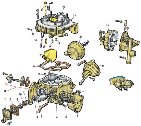
Pierburg/Solex 2E3 Carburetor Components 1 – fast idle speed adjusting screw; 2 – lever; 3 – mixture quality adjusting screw; 4 – carburetor body; 5 – solenoid valve; 6 – stop screw; 7 – accelerator pump cover; 8 – pump diaphragm; 9 – spring; 10 – valve seat; 11 – accelerator pump valve; 12 – power enrichment valve; 13 – accelerator pump nozzle; 14 – carburetor cover gasket; 15 – float; 16 – main jet, first chamber; 17 – needle valve; 18 – filter; 19 – main jet, second chamber; 20 – float pin; 21 – idle jet; 22 – power enrichment tube; 23 – carburetor cover; 24 – choke pneumatic actuator; 25 – automatic choke; 26 – choke cover; 27 – second chamber throttle pneumatic actuator
If the 12-mode power economizer is removed during carburetor disassembly, it must be replaced. Checking the solenoid valve To check the solenoid valve 5, disconnect the wire from it. Connect a wire from the solenoid valve to the positive terminal of the battery. A click should be heard. If there is no click, the valve is faulty and must be replaced. Adjusting the choke valve clearance PROCEDURE 1. Remove the cover 26 of the starting device. 2. Open the throttle valve of the primary barrel and turn the choke cam 1 (see figure Adjusting the engine fast idle speed) so that the fast idle adjusting screw 2 rests on the highest step of the cam.
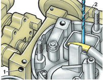
3. Through hole 1, use a screwdriver to push the choke pneumatic actuator rod fully in until it stops. Measure the clearance between the choke valve and the venturi. It must be 2.0±0.1 mm. The clearance can be measured with drill bit 2 of 2 mm diameter. If the clearance differs from the specified value, insert a screwdriver into hole 1 and adjust the clearance by turning the adjusting screw. Adjusting the accelerator pump PROCEDURE 1. Remove the carburetor. 2. Remove the carburetor cover, fill the float chamber with fuel, and install the carburetor cover. 3. Turn the cam 1 (see figure Adjusting the engine fast idle speed) so that it does not touch screw 2. 4. Place a graduated cylinder with a funnel under the carburetor. 5. Holding cam 1 in this position, smoothly open the throttle valve of the primary barrel from stop to stop 10 times, taking 1 s for each stroke and then pausing for 3 s, to actuate the accelerator pump. 6. Measure the amount of fuel in the graduated cylinder and divide by 10. This gives the amount of fuel delivered by the accelerator pump per stroke. This value must be 1.0±0.15 cm3.

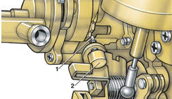
7. If the result differs from the specified value, adjust the accelerator pump output.
To do this, loosen screw 1 and turn cam 2. Turning the cam toward "A" increases the pump output; turning it toward "B" decreases the output.
Tighten screw 1 and secure it with paint. Checking the automatic choke To check the automatic choke, disconnect the wire of the device from the connector block. Connect a test lamp to the device wire. Connect the second lead of the lamp to the positive terminal of the battery. The lamp must light. If the lamp does not light, the starting device is faulty and must be replaced. Make sure that the marks on the cover and the body of the starting device are aligned.
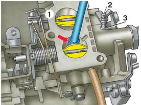
Adjusting the opening of the secondary throttle valve 1 – throttle lever; 2 – stop screw; 3 – stop; the arrow shows the wooden rod
The throttle valve position is set at the factory and does not require adjustment during operation. If the adjustment has been disturbed, it can be restored as follows: PROCEDURE 1. Fully open the throttle valve of the primary barrel and hold it in this position with a wooden rod.
2. Turn lever 1 so that the secondary throttle valve closes. Secure lever 1 with a rubber band, as shown in the figure. 3. Back out stop screw 2 so that it does not touch stop 3. 4. Turn screw 2 until it contacts stop 3, then turn it an additional quarter turn (90°). Secure screw 2 with paint. 5. Remove the rubber band and remove the wooden rod. Both throttle valves must be closed.
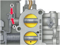
6. Measure the internal clearance "A" and the external clearance "B". Clearance "A" must be 0.4±0.1 mm, clearance "B" must be 1.0±0.1 mm. 7. If the clearances differ from the specified values, adjust them by bending the fork ends of lever 1. Checking the choke pneumatic actuator PROCEDURE 1. Remove the air cleaner. 2. Start the engine and let it run at idle. 3. Smoothly close the choke valve by hand until noticeable resistance is felt. At this point the clearance between the choke valve and the venturi must be approximately 4 mm. 4. If no resistance is felt, check the vacuum hoses for cracks. 5. If the hoses are intact, connect a vacuum gauge and a vacuum pump to the pneumatic actuator. Create a vacuum of 300 mbar in the actuator. If the actuator is serviceable, the vacuum must not drop for 2 min. If the vacuum drops, the actuator is leaking and must be replaced. Checking the secondary throttle valve pneumatic actuator PROCEDURE 1. Connect a vacuum gauge and a vacuum pump to the pneumatic actuator. 2. Create a vacuum of 50 mbar in the actuator. If the vacuum does not drop for 2 min, the actuator is sealed. Otherwise, replace the pneumatic actuator.
Adjusting the engine fast idle speed 1 – choke cam; 2 – engine fast idle speed adjusting screw
Adjustment is performed on a warm engine with correctly set ignition timing and adjusted idle speed, in the following order: PROCEDURE 1. Remove the air cleaner and disconnect vacuum hose 24 (see figure Air cleaner for engines with 1.1 and 1.3 L displacement). 2. Connect a diagnostic tachometer to the engine. 3. Start the engine and open the throttle valve of the primary barrel until the crankshaft speed reaches approximately 2500 min-1. 4. Turn cam 1 to its stop. Then turn the throttle valve so that adjusting screw 2 rests on the second highest step.
5. Check the engine speed on the tachometer. It must be 2000±100 min-1. If the speed differs from the specified value, adjust it with screw 2. Adjusting the idle speed
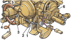
Adjusting screws 1 – mixture quantity adjusting screw; 2 – mixture quality adjusting screw; 3 – heating element; 4 – solenoid valve; 5 – choke pneumatic actuator; 6 – automatic choke
Adjustment is performed on a warmed-up engine with valve train clearances adjusted and ignition timing correctly set, in the following sequence: PROCEDURE 1. Switch off all electrical consumers (headlights, fan, radio, etc.). 2. Disconnect the crankcase ventilation hose from the air cleaner and plug it. 3. Connect a diagnostic tachometer and exhaust gas analyzer. 4. Turn cam 1 (see fig. Engine Idle Speed Adjustment) so that it does not touch screw 2. 5. Using mixture quantity adjusting screw 1, adjust idle speed to 800±50 rpm. 6. Using mixture quality adjusting screw 2, set the CO content in exhaust gases to 3.0±0.5%. Check and, if necessary, correct the CO content in exhaust gases.
Test yourself
A quick Volkswagen Golf quiz: every answer comes with an explanation and a link to the manual page.