Weber 32TLA Carburetor Adjustment
PROCEDURE
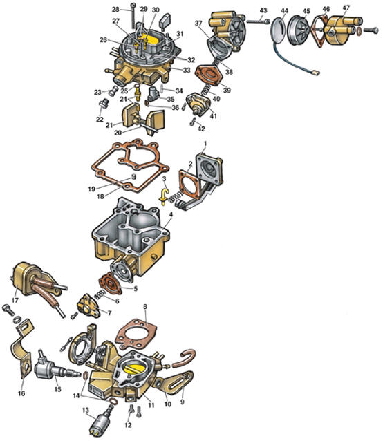
Weber 32TLA Carburetor Components 1 – accelerator pump cover; 2 – accelerator pump diaphragm; 3 – accelerator pump nozzle; 4 – carburetor body; 5 – valve diaphragm; 6 – spring; 7 – transitional mixture enrichment valve cover; 8 – gasket; 9 – engine starting speed adjusting screw; 10 – throttle lever; 11 – throttle valve body; 12 – mixture quality (composition) adjusting screw; 13 – solenoid valve; 14 – O-ring; 15 – mixture quantity adjusting screw; 16 – bracket; 17 – two-way valve; 18 – gasket; 19 – main fuel jet; 20 – float pivot pin; 21 – float; 22 – plug; 23 – filter; 24 – needle valve; 25 – O-ring; 26 – auxiliary fuel jet; 27 – emulsion tube; 28 – cover mounting bolt; 29 – air jet; 30 – idle fuel jet; 31 – choke valve shaft; 32 – plug; 33 – carburetor cover; 34 – pin; 35 – venturi; 36 – venturi gasket; 37 – automatic choke; 38 – spring; 39 – diaphragm; 40 – spring; 41 – choke vacuum actuator cover; 42 – choke valve adjusting screw; 43 – automatic choke mounting bolt; 44 – heating element; 45 – choke cover; 46 – cover retaining ring; 47 – cover
This carburetor is similar in design to the 1B3 carburetor. Float Chamber Fuel Level Adjustment
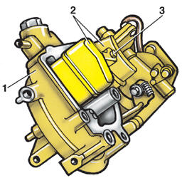
Weber 32TLA Float Position Check 1 – carburetor cover; 2 – float; 3 – main fuel jet; A – dimension from the carburetor cover mating surface to the lower edge of the float
The fuel level is adjusted by the float position. To check the float position, remove the carburetor cover and install it at a 45° angle to the horizontal. Measure dimension "A". This dimension must be 28±1.0 mm. If the measured dimension differs from the specified value, bend the float. Accelerator Pump Adjustment
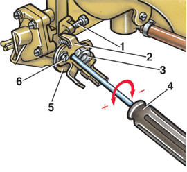
Accelerator Pump Adjustment 1 – throttle valve opening adjusting screw; 2 – throttle lever; 3 – nut; 4 – screwdriver; 5 – accelerator pump drive cam; 6 – screw
To check and adjust the accelerator pump output, the carburetor must be removed from the engine. PROCEDURE: 1. Remove cover 47 (see fig. Weber 32TLA Carburetor Components). 2. Remove the three bolts and remove ring 46, automatic choke cover 45 and heating element 44. 3. Pull lever 3 back with a rubber band (fig. 3.21 Fast Idle Speed Adjustment) so that cam 2 disengages from adjusting screw 1. 4. Remove the carburetor cover, fill the float chamber with fuel and install the carburetor cover. 5. Place a measuring cylinder with a funnel under the carburetor. 6. Slowly open the throttle valve from stop to stop 10 times, taking 1 s for each stroke and then pausing for 3 s, to actuate the accelerator pump. 7. Measure the fuel quantity in the measuring cylinder and divide by 10. This gives the fuel quantity delivered by the accelerator pump per stroke. This value must be 1.05±0.15 cm3. 8. If necessary, adjust the accelerator pump output. To do this, tighten screw 6. Remove the lock and loosen nut 3. Loosen screw 2 and turn cam 5 with a screwdriver. Turning cam 5 toward "+" increases accelerator pump output, and toward "-" decreases it. Tighten nut 3 and install the lock. Throttle Valve Opening Adjustment PROCEDURE: 1. Remove covers 47 (see fig. Weber 32TLA Carburetor Components), 45 and heating element 44. 2. Pull lever 3 back with a rubber band (fig. 3.21 Fast Idle Speed Adjustment). 3. Remove the protective cap from adjusting screw 1 (see fig. Accelerator Pump Adjustment). 4. Back out screw 1 until a gap appears between it and lever 2. 5. Turn screw 1 in until it contacts lever 2, then turn it in a further quarter turn (90°). 6. Install a new protective cap on the screw. 7. Adjust the idle speed.
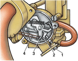
Fast Idle Speed Adjustment 1 – fast idle speed adjusting screw; 2 – cam; 3 – choke lever; 4 – rubber band
Adjust on a warmed-up engine with ignition timing correctly set and idle speed adjusted, as follows: PROCEDURE: 1. Remove the air cleaner and disconnect vacuum hose 24 (see fig. Air Cleaner for 1.1 and 1.3 L Displacement Engines). 2. Connect a diagnostic tachometer to the engine. 3. Remove covers 47 (see fig. Weber 32TLA Carburetor Components), 45 and heating element 44. 4. Position adjusting screw 1 on the step of cam 2.
5. Pull lever 3 back with rubber band 4 so that the choke valve is fully open. 6. Start the engine without pressing the accelerator pedal. 7. Check engine speed on the tachometer; it must be 2000±100 min-1. If necessary, adjust engine speed with screw 1. Idle Speed Adjustment Adjust on a warmed-up engine with valve train clearances adjusted, ignition timing correctly set and choke fully open, as follows: PROCEDURE: 1. Switch off all electrical consumers (headlights, fan, radio, etc.). 2. Disconnect the crankcase ventilation hose from the air cleaner and plug it. 3. Connect a diagnostic tachometer and exhaust gas analyzer. 4. Using mixture quantity adjusting screw 15 (see fig. Weber 32TLA Carburetor Components), set crankshaft speed within 800 ± 50 min-1.

5. Using mixture quality adjusting screw 1, set the CO content in the exhaust gas to 2.0±0.5%. 6. Check and, if necessary, restore the idle speed. Check and, if necessary, restore the CO content in the exhaust gas.

Choke Valve Clearance Adjustment 1 – cam; 2 – fast idle speed adjusting screw; 3 – choke pneumatic actuator rod
PROCEDURE: 1. Remove cover 47 (see fig. Weber 32TLA Carburetor Components), 45 and element 44. 2. Position adjusting screw 2 in the upper step of cam 1.
3. Using a screwdriver, move rod 3 in the direction of the arrow.

4. Measure the clearance between the choke valve and the throat wall; it must be 2.5±0.2 mm. Make sure spring 2 is not compressed. The clearance can be measured with a drill bit 1 of suitable diameter. If the clearance differs from the specified value, adjust it with screw 3.
Test yourself
A quick Volkswagen Golf quiz: every answer comes with an explanation and a link to the manual page.