Carburetor
PROCEDURE
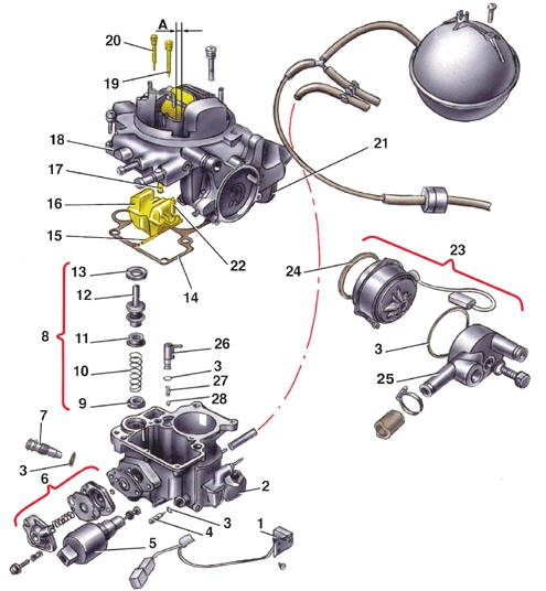
1B3 Carburetor Components 1 – heating element; 2 – carburetor body; 3 – O-ring; 4 – mixture quality adjusting screw; 5 – solenoid valve; 6 – power enrichment (economizer) valve; 7 – mixture quantity adjusting screw; 8 – accelerator pump; 9 – valve seat; 10 – spring; 11 – pump piston cup; 12 – accelerator pump piston; 13 – piston guide; 14 – gasket; 15 – float pivot pin; 16 – float; 17 – main fuel jet; 18 – carburetor cover; 19 – economizer fuel jet; 20 – idle fuel jet; 21 – choke pneumatic actuator; 22 – needle valve; 23 – automatic choke device; 24 – gasket; 25 – cover; 26 – accelerator pump nozzle; 27 – spring; 28 – ball valve of the nozzle; A – choke valve starting clearance
Removal and Installation PROCEDURE 1. Disconnect the cable from the negative terminal of the battery. 2. Drain approximately half of the coolant from the engine cooling system (see
subsection 2.4.1). 3. Remove the air filter (see subsection 3.1.2).
4. Disconnect the accelerator cable from the carburetor. 5. Disconnect the cooling system hoses from the carburetor (if equipped).
6. Disconnect the electrical wires, fuel hoses and vacuum hoses from the carburetor. 7. Unscrew the bolts or nuts securing the carburetor to the intake manifold and remove the carburetor. Remove the carburetor gasket. Install the carburetor in the reverse order. When installing the carburetor, replace the gaskets. Disassembly and Assembly PROCEDURE 1. Disconnect the accelerator pump linkage. 2. Unscrew the bolts securing the carburetor cover to the body and remove cover 18.
Remove gasket 14. 3. Remove float pivot pin 15, remove float 16 and take out needle valve 22. 4. Unscrew main fuel jet 17. 5. Unscrew idle fuel jet 20 and economizer fuel jet 19. 6. Remove automatic choke device 23. 7. Remove accelerator pump 8. 8. Unscrew solenoid valve 5. 9. Remove heating element 1. 10. Unscrew accelerator pump nozzle 26, unscrew spring 27 and ball valve 28. 11. Unscrew mixture quality adjusting screw 4 and mixture quantity adjusting screw 7.
12. Remove power enrichment economizer 6. Wash all carburetor parts in gasoline. If heavy resinous deposits are present, wash the parts in acetone or lacquer thinner. Do not clean the jets with wire, even soft wire, as this will disturb their calibration. Blow out the washed parts and carburetor passages with compressed air. Replace torn gaskets and O-rings, as well as any defective parts. Assemble the carburetor in reverse order. Disassembly and assembly of other carburetor models is carried out in the same way. When assembling the carburetor, note the following: Carburetor Pierburg/Solex 1B3: To check the serviceability of solenoid valve 5 (see Figure Carburetor 1B3 Parts), connect 12 V power to the valve terminal and connect the valve body to ground. The valve pin should retract 3–4 mm.
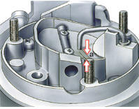
Carburetors Pierburg/Solex 2E2 and 2E3
When installing the fuel tube, check clearance "a" between the end of the tube and the surface of the choke valve. It should be 0.7–1.3 mm. If the clearance differs, carefully bend the tube.
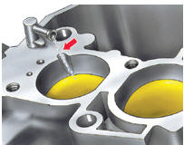
Carburetor Pierburg/Solex 31P1C-7
When installing the accelerator pump nozzle, it must be positioned so that fuel flows into the recess.
To check the serviceability of solenoid valve 12 (see Figure Carburetor 31P1C-7 Parts), depress the valve pin by 3–4 mm. Then connect 12 V to the valve terminal and connect the valve body to ground. A click should be heard and the pin should extend. If the carburetor is equipped with a fuel cut-off valve (such as valve 17), check it in the same way as valve 17.
Test yourself
A quick Volkswagen Golf quiz: every answer comes with an explanation and a link to the manual page.