Adjusting Carburetor Pierburg/Solex 31P1C-7
PROCEDURE
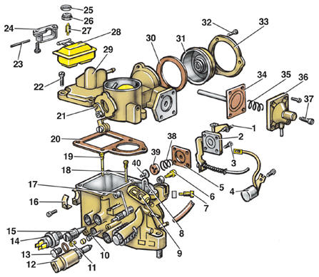
31P1C-7 Carburetor Components 1 – accelerator pump adjusting screw; 2 – accelerator pump cover; 3 – cover mounting screw; 4 – heating element; 5 – accelerator pump diaphragm; 6 – auxiliary fuel jet; 7 – idle jet; 8 – accelerator pump nozzle; 9 – engine start idle speed adjusting screw; 10 – mixture quality (composition) adjusting screw; 11 – main fuel jet; 12 – solenoid valve; 13 – plug; 14 – heating element thermal switch; 15 – mixture quantity adjusting screw; 16 – choke rod bracket; 17 – roller; 18 – air jet with emulsion tube; 19 – auxiliary air jet; 20 – gasket; 21 – choke valve lever; 22 – cover mounting screw; 23 – float axle; 24 – float axle bracket; 25 – adjusting washer; 26 – valve seat; 27 – valve needle; 28 – float; 29 – carburetor cover; 30 – O-ring; 31 – automatic starting device cover; 32 – cover mounting bolt; 33 – cover retaining ring; 34 – choke valve pneumatic actuator diaphragm; 35 – diaphragm spring; 36 – pneumatic actuator cover; 37 – choke valve clearance adjusting screw; 38 – spring; 39 – valve seat; 40 – accelerator pump valve
Removal, Installation and Adjustment of Carburetor Choke Cable
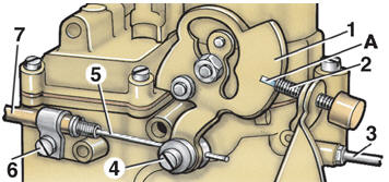
Choke Cable Attachment to 31P1C-7 Carburetor 1 – choke valve lever; 2 – engine start idle speed adjusting screw; 3 – throttle valve control lever; 4 – cable clamp screw; 5 – choke cable; 6 – choke cable bracket; 7 – choke cable sheath; A – mark on choke cable lever
PROCEDURE 1. Disconnect the negative battery cable. 2. Remove the air filter. 3. Unscrew screw 4 and the bracket screw 6. 4. Remove the cable from bracket 6 and lever 1. 5. Remove the shelf under the instrument panel on the driver's side. 6. Disconnect the cable mounting from the front panel. 7. Pull the cable into the passenger compartment. Install the cable in reverse order. Adjust the cable before installing the air filter.
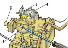
Choke Valve Clearance Adjustment 1 – choke valve pneumatic actuator rod; 2 – choke valve clearance adjusting screw; 3 – drill bit; 4 – carburetor choke valve
PROCEDURE 1. On a carburetor with manual choke, disconnect cable 5 (see figure Choke Cable Attachment to 31P1C-7 Carburetor) from lever 1. Turn lever 1 so that the choke valve closes. Remove cover 31 (see figure 31P1C-7 Carburetor Components) together with the bimetal spring. 2. On a carburetor with automatic choke, remove cover 31 with the bimetal spring. Close the choke valve. 3. Push rod 1 of the choke valve pneumatic actuator diaphragm all the way in.
4. Measure the clearance between the choke valve and the bore. It must be 1.6–2.0 mm. The clearance can be measured with a drill bit.
5. If the clearance is outside the specified range, adjust it by turning screw 2, after removing the protective cap from the screw. 6. Install cover 31 (see figure 31P1C-7 Carburetor Components) so that the mark on the cover aligns with the mark on the carburetor body. 7. On carburetors with manual choke, connect cable 5 (see figure Choke Cable Attachment to 31P1C-7 Carburetor).
Engine Start Idle Speed Adjustment
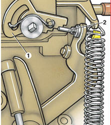
1 – choke valve lever; 2 – engine start idle speed adjusting screw;
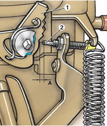
A – clearance between the lever and the adjusting screw with the choke valve fully open
On a carburetor with manual choke, adjust as follows: PROCEDURE 1. Connect a diagnostic tachometer to the engine. 2. Pull the choke control knob fully out. 3. Start the engine and check the engine start idle speed on the tachometer; it must be 2600±100 min⁻¹. 4. If the speed differs from the specified value, adjust it by turning screw 2 (see figure Choke Cable Attachment to 31P1C-7 Carburetor), after removing its protective cap (if fitted). On a carburetor with automatic choke, adjust as follows: PROCEDURE 1. Connect a diagnostic tachometer to the engine. 2. Start the engine and set screw 2 on the third tooth of lever 1.
3. Check the engine start idle speed on the tachometer; it must be 2600±100 min⁻¹. 4. If the speed differs from the specified value, adjust it by turning screw 2, after removing its protective cap. 5. Fully open the choke valve and measure clearance A between lever 1 and adjusting screw 2. Clearance A must equal 0.2 mm.
Accelerator Pump Adjustment
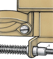
1 – accelerator pump rod nut;
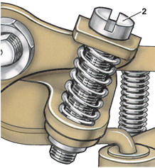
2 – accelerator pump adjusting screw
PROCEDURE 1. Remove the carburetor. 2. Remove the carburetor cover, fill the float chamber with fuel and install the carburetor cover. 3. Place a graduated measuring cylinder with a funnel under the carburetor. 4. Fully open the choke valve and secure it in this position, for example, by tying it with wire. 5. Slowly turn the throttle valve from stop to stop 10 times, taking approximately 3 s for each stroke, thereby actuating the accelerator pump. 6. Measure the amount of fuel in the measuring cylinder and divide by 10. This gives the amount of fuel delivered by the accelerator pump per stroke. This value must be 0.85–1.1 cm3. 7. If necessary, adjust the accelerator pump output with nut 1 or screw 2. 8. Make sure that fuel from the accelerator pump nozzle is injected into the gap between the throttle valve and the throat. If necessary, bend the accelerator pump nozzle. Idle speed adjustment. Adjust on a warmed-up engine with the valve train clearances adjusted and the ignition timing correctly set, in the following order: PROCEDURE 1. Switch off all electrical consumers. 2. Disconnect the crankcase ventilation hose from the air cleaner and plug it. 3. Connect a diagnostic tachometer and gas analyzer. 4. Using mixture quantity adjusting screw 15 (see figure Weber 31P1C-7 Carburetor Components), adjust the crankshaft speed within 950±50 min-1. 5. Using mixture quality (composition) adjusting screw 10, set the carbon monoxide (CO) content in the exhaust gas to no more than 1±0.5%. 6. Check and, if necessary, restore the idle speed. Check and, if necessary, restore the CO content in the exhaust gas. Checking the heating element. The heating element 4 (see figure Weber 31P1C-7 Carburetor Components) can be checked by disconnecting its wire from the connector block on top of the carburetor. Connect a bulb to the element wire, and connect the second bulb wire to the positive battery terminal. The bulb must light. If the bulb does not light, the heating element is faulty and must be replaced.
Test yourself
A quick Volkswagen Golf quiz: every answer comes with an explanation and a link to the manual page.