Brake, brake mechanics. Rear brake
- Assembly overview - rear brake, drum brake version
- Assembly overview – brake shoes
- Removing and installing brake backplate
- Removing and installing gasket for brake backplate
- Removing and installing brake shoes
- Removing and installing brake drum
Assembly overview - rear brake, drum brake version
Assembly overview - rear brake, drum brake version
The overview is shown for the left side of the vehicle as an example.
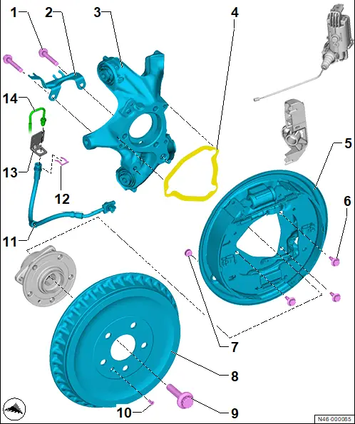
1 - Multi-point socket head bolt
❏ Qty. 4
❏ N.108.626.01
❏ Renew after removing
❏ M10 x 58
❏ 50 N·m +180°
2 - Bracket
3 - Wheel bearing housing
❏ → Running gear, axles, steering; Rep. gr.42; Wheel bearing, trailing arm; Assembly overview – wheel bearing
4 - Gasket
❏ → Rep. gr.46; Removing and installing gasket for brake backplate
5 - Brake backplate with brake shoes
❏ → Rep. gr.46; Removing and installing brake backplate
6 - Multi-point socket head bolt
❏ Qty. 3
❏ M8 x 25
❏ 20 N·m +45°
7 - Plug
8 - Brake drum
❏ Wear limit → Rep. gr.00; Test and adjustment values
9 - Bolt
❏ → Running gear, axles, steering; Rep. gr.42; Wheel bearing, trailing arm; Assembly overview – wheel bearing
10 - Torx bolt
❏ M6 x 16
❏ 8 N·m
11 - Brake hose with banjo union and banjo bolt
❏ Ensure correct installation position
❏ Banjo bolt on wheel brake cylinder: 45 N·m
12 - Clip
13 - Retainer
14 - Brake line
❏ 14 N·m
Assembly overview – brake shoes
Assembly overview – brake shoes
The overview is shown for the left side of the vehicle as an example.
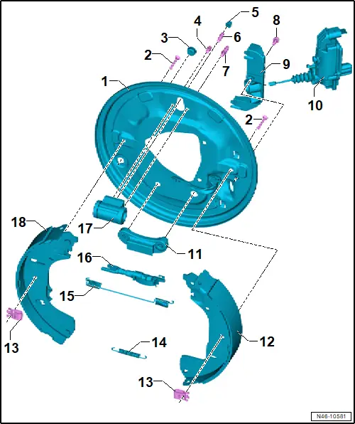
1 - Brake carrier
2 - Hold-down pin
3 - Sealing plug
4 - Bolt
❏ 10 N·m
5 - Protective cap for bleeder screw
6 - Bleeder valve
❏ 10 N·m
7 - Pin
❏ For brake hose adjustment
8 - Bolt
❏ 8 N·m
9 - Bracket for parking brake motor
10 - Left parking brake motor -V282-/right parking brake motor -V283-
❏ → Rep. gr.46; Removing and installing parking brake motor [V282]/[V283]
11 - Lower support
12 - Brake shoe
❏ Check thickness of brake linings → Booklet; Front and rear brake pads/linings: Checking thickness
❏ Renew on both sides
❏ Wear limit → Rep. gr.00; Test and adjustment values
❏ → Rep. gr.46; Removing and installing brake shoes
13 - Retaining clip
❏ For locking brake shoe
❏ Qty. 2
14 - Lower return spring
15 - Upper return spring
16 - Automatic adjuster
❏ Left-side version with annular groove on coarse adjuster
❏ With adjustment screw
17 - Wheel brake cylinder
❏ → Rep. gr.47; Check wheel brake cylinder for leaks
18 - Brake shoe with lever for parking brake
❏ Check thickness of brake linings → Booklet; Front and rear brake pads/linings: Checking thickness
❏ Renew on both sides
❏ Wear limit → Rep. gr.00; Brake technical data
❏ → Rep. gr.46; Removing and installing brake shoes
Removing and installing brake backplate
Removing and installing brake backplate
Special tools and workshop equipment required
♦ hook -VAS 281 007-
Removal and installation are described for left side of vehicle as an example.
Removing
– Remove wheel bearing unit → Running gear, axles, steering; Rep. gr.42; Wheel bearing, trailing arm; Removing and installing wheel bearing unit .
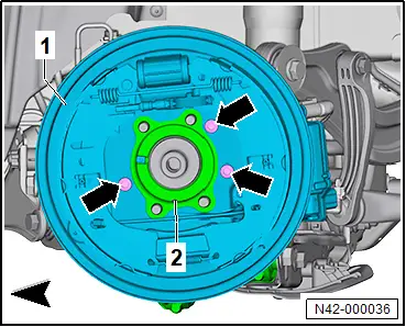
– Unscrew bolt -5-.
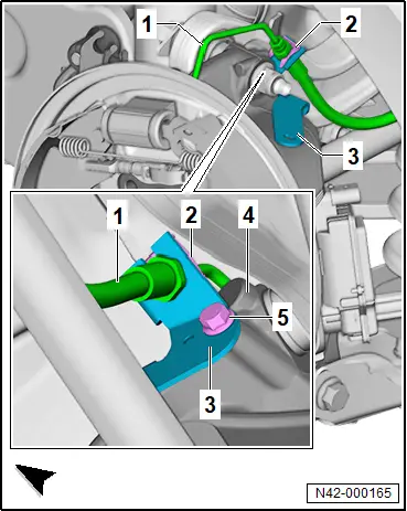
– Unscrew bolts -2-.
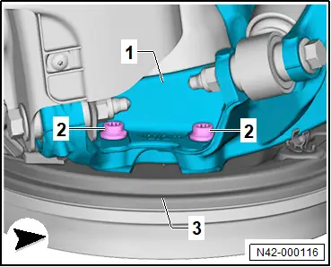
– Unscrew bolts -arrows-.
– Detach brake backplate -1- from wheel bearing housing -2-.
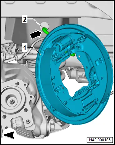
– Secure brake backplate -1- to body -arrow- using hook -VAS 281 007- -2-.
Installing
Install in reverse order of removal, observing the following:
– Renew gasket for brake backplate → Running gear, axles, steering; Rep. gr.42; Wheel bearing, trailing arm; Removing and installing gasket for brake backplate.
Tightening torques
♦ → Brake system; Rep. gr.46; Rear brake; Assembly overview – rear brake, drum brake
♦ → Brake system; Rep. gr.46; Rear brake; Assembly overview – brake shoes
Removing and installing gasket for brake backplate
Removing and installing gasket for brake backplate
Special tools and workshop equipment required
♦ Adhesive strip remover -VAS 6349-
♦ guide bolt -T10406-
♦ template -T10669-
Removal and installation are described for the left vehicle side as an example.
Removing
– Remove brake backplate → Brake system; Rep. gr.46; Rear brake; Removing and installing brake backplate.
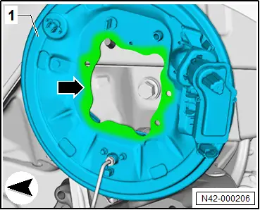
– Remove sealant residue -2- using adhesive strip remover -VAS 6349-.
– Clean sealing surfaces using commercially available methylated spirits.
Important
● Cleaned surfaces must be free of greasing and sealing agents.

– Remove sealant residue -2- using adhesive strip remover.
– Clean sealing surfaces using commercially available methylated spirits.
Important
● Cleaned surfaces must be free of greasing and sealing agents.
Installing
Install in reverse order of removal, observing the following:
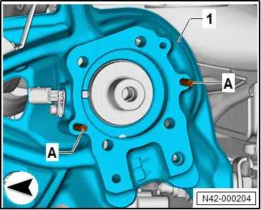
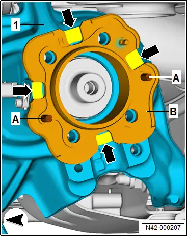
– Screw guide pin -T10406- -A- into holes of wheel bearing housing -1-.
Important
● If gaskets -1- were not fitted at factory, retrofitting must always be carried separately for each axle.
– Insert gasket -1- into side “L” of template -T10669- -B-.
Important
● Note markings on template -B- for relevant side of vehicle.
– Pull off protective film.
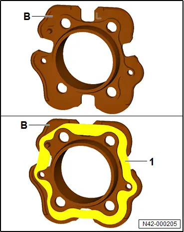
– Fit template -B- over guide pins -A- onto wheel bearing housing -1-.
– Press on gasket in marked areas -arrows-.
– Remove template -B-.
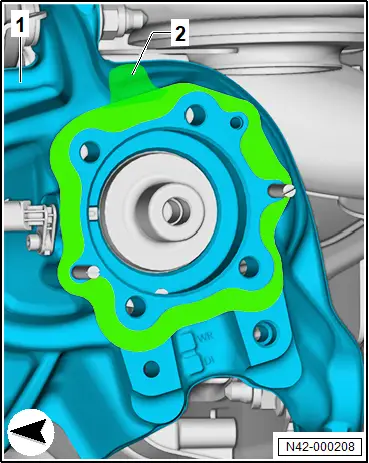
– Press on gasket -2- over entire circumference.
– Pull off protective film -2-.
Removing and installing brake shoes
Removing and installing brake shoes
Special tools and workshop equipment required
♦ Assembly tool -T30114-
♦ assembly device -T10635-
♦ assembly pliers -T10623-
 WARNING
Health hazard due to poisonous dust from brake system.
Risk of irreversibly deposited dust particles in the lungs. Risk of respiratory health problems.
– Do not blow out brake system with compressed air.
Removal and installation are described for the left side of vehicle as an example.
Important
● Do not operate brake when system is open.
Removing
– Remove brake drum → Rep. gr.46; Removing and installing brake drum.
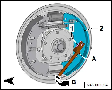
– Turn clip -1-.
– Use assembly tool -T30114- -A- to release and pull out clip -1- in direction of -arrow B-. Press against pin from behind while doing so.
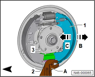
– Using commercially available water pump pliers -A-, lever brake shoe -1- in direction of -arrow B- out of reaction block -3-.
– Put brake shoe -1- in direction of -arrow C- before reaction block -3-.
– Unhook lower return spring -2-.
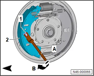
– Bring clip -1- in position.
– Use assembly tool -T30114- -A- to release and pull out clip -1- in direction of -arrow B-. Press against pin from behind while doing so.
 NOTICE
Risk of damage to wheel brake cylinder, boot and automatic adjuster through improper handling.
Any damage will have a negative effect on the function of the automatic adjuster and the brake.
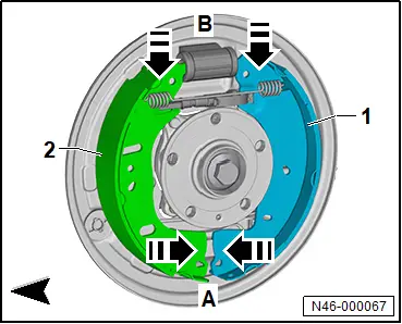
– Remove both brake shoes.
– Press together brake shoes -1- and -2- in direction of -arrows A-, and pull in direction of -arrows B-.
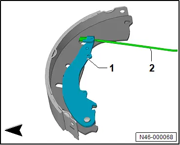
– Detach handbrake cable -2- from handbrake lever -1-.
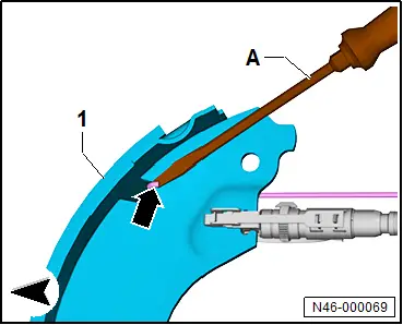
– Lever upper return spring -arrow- out of brake shoe -1- using commercially available screwdriver -A-.
Installing
Install in reverse order of removal, observing the following:
 CAUTION
Risk of injury from chemical cleaning agents. Chemical cleaning agents can be highly flammable and can cause eye and skin irritation.
– Wear safety goggles, safety gloves and a respirator mask.
– Observe safety data sheet and instructions for use of the cleaning agent.
– Clean brake system.
Important
● Use only commercially available methylated spirits for cleaning the brake system.
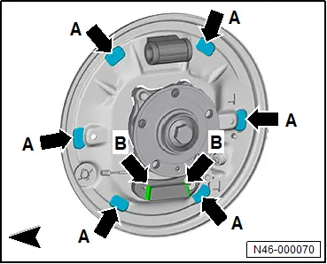
11"- brake system models
– Grease contact surfaces -arrows A- and -arrows B- with lubricating paste. For allocation, see → Electronic parts catalogue (ETKA).
All vehicles (continued)
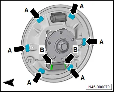
13"- brake system models
– Grease contact surfaces -arrows A- with lubricating paste. For allocation, see → Electronic parts catalogue (ETKA).
All vehicles (continued)
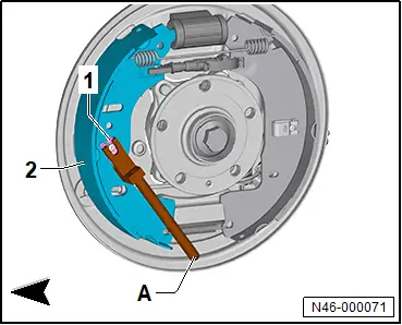
– Attach handbrake cable -2- to handbrake lever -1-.

– Install brake shoe -2- with handbrake lever.
– Use assembly tool -T30114- -A- to insert clip -1-. Press against pin from behind while doing so.
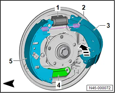
– Insert upper return spring -2- into brake shoes -3- and -5-.
– Position brake shoe -3- on wheel brake cylinder -1-, swing in direction of -arrow-, and place it in front of reaction block -4-.
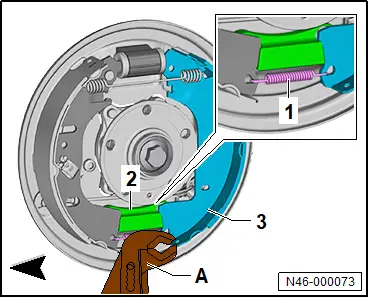
– Attach lower return spring -1-, and lever brake shoe -3- into reaction block -2- using commercially available water pump pliers -2-.
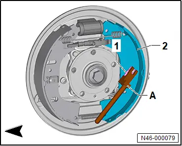
– Use assembly tool -T30114- -A- to insert clip -1-. Press against pin from behind while doing so.
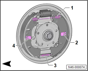
– Turn clips -2- and -4- to horizontal, and align return springs at top -1- and bottom -3- in position.
– Note that the automatic adjuster has a fine mechanism.
 NOTICE
Risk of damage to automatic adjuster from improper handling.
Deformations can negatively influence the function of the automatic adjuster.
– Handle components with care.
– Do not deform components.
– No adjustment on gear wheel.
Important
● To ensure that the brake functions optimally, pre-adjustment of the automatic adjuster is required. The automatic adjuster must be free to rotate and it should be possible to install it without applying force.
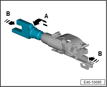
– Turn bolt in direction of -arrow A- for “rough adjustment”.
– Push regulator in direction of -arrow B- to activate “fine adjustment”.
 NOTICE
Malfunction and risk of damage to the rear brake due to incorrect adjustment of the automatic adjuster.
– The automatic adjuster must be adjusted manually to attain the requisite diameter at the brake shoes.
– Screw automatic adjuster in or out, in such a way that it sits between both brake shoes with slight pretension thus adjusting the rear brake.
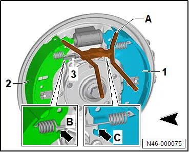
– Press brake shoes -1- and -2- apart using assembly pliers -T10623- -A-.
– Position automatic adjuster in recesses -arrow B- and -arrow C-.
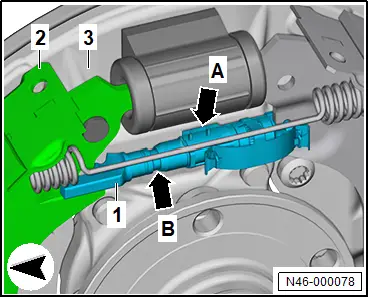
– Note installation position of automatic adjuster -1-.
Important
● Thermo clip -arrow A- must point towards brake backplate -3- while threaded side -arrow B- points towards brake shoe -2- with handbrake lever.
● Shorter guide of threaded side -arrow B- must point towards brake backplate -3-.
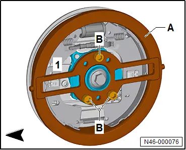
– Fit assembly device -T10635- -A- to wheel hub -1- using enclosed bolts -B-.
Important
● Bolts -B- of assembly device -T10635- -A- must be screwed into through-holes.
– Using assembly pliers -T10623- -B-, repeatedly push brake shoes -1- and -2- in direction of -arrows- until no adjustment is visible nor audible on automatic adjuster.
– Remove setting tool -T10635- -A-.
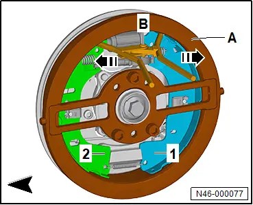
– Install brake drum → Rep. gr.46; Removing and installing brake drum.
If the brake shoes have been renewed:
– Check the brake fluid level → Booklet.
All vehicles (continued)
– Check function of brake.
– Carry out road test.
Tightening torques
♦ → Rep. gr.46; Assembly overview - rear brake, drum brake version
Removing and installing brake drum
Removing and installing brake drum
 WARNING
Health hazard due to poisonous dust from brake system.
Risk of irreversibly deposited dust particles in the lungs. Risk of respiratory health problems.
– Do not blow out brake system with compressed air.
Removal and installation are described for the left side of vehicle as an example.
Important
● Do not operate the brake when the system is open.
Removing
– → Running gear, axles, steering; Rep. gr.44; Wheels, tyres; Removing wheel.
– Carry out function “Brake service, rear” using → Vehicle diagnostic tester → Rep. gr.00; Access to diagnoses.
– Unscrew bolt -2-, and remove brake drum -1-.

Installing
Install in reverse order of removal, observing the following:
– Carry out function “Brake service, rear” using → Vehicle diagnostic tester → Rep. gr.00; Access to diagnoses.
Tightening torques
♦ → Rep. gr.46; Assembly overview - rear brake, drum brake version