Windscreen wipewash system. Windscreen wiper system

In this manual: Windscreen wipewash system. Windscreen wiper system
Technical data. Panel gaps - front — 1Body front. Lock carrier — 1Body front. Wings — 1Body front. Bulkhead — 1Bonnet, flaps, cab, central locking. Bonnet — 1Bonnet, flaps, cab, central locking. Rear lid — 1Bonnet, flaps, cab, central locking. Charging flap unit — 1Front door, central locking. Door — 1Front door, central locking. Door components — 1Front door, central locking. Central locking — 1Rear door,sliding door,wing doors,central locking. Door — 1Rear door,sliding door,wing doors,central locking. Door components — 1Sliding roof. Sliding sunroof — 1Bumper. Bumper, front — 1Bumper. Bumper, rear — 1Glazing & window mechanism. Repair notes — 1Glazing & window mechanism. Windscreen — 1Glazing & window mechanism. Rear windscreen — 1Glazing & window mechanism. Side windows — 1Glazing & window mechanism. Door windows — 1Exterior equipment. Spoiler — 1Exterior equipment. Mouldings, trims, extensions — 1Exterior equipment. Underbody cladding — 1Exterior equipment. Roof moulding and roof railing — 1Exterior equipment. Exterior mirror — 1Exterior equipment. Wheel housing liner — 1Exterior equipment. Lettering and emblems — 1Exterior equipment. Bicycle carrier — 1Exterior equipment. Trim film and protective film — 1Interior equipment. Compartments & covers — 1Interior equipment. Equipment — 1Interior equipment. Centre console — 1Interior equipment. Front centre armrest — 1Interior equipment. Interior mirror — 1Passenger protection. Seat belts — 1Passenger protection. Child seat anchors — 1Passenger protection. Airbag system — 1Passenger protection. Airbag control unit — 1Passenger protection. Front airbag, driver side — 1Passenger protection. Front passenger airbag — 1Passenger protection. Side airbags — 1Passenger protection. Curtain airbags — 1Passenger protection. Airbag crash sensors — 1Passenger protection. Seat occupied recognition — 1Trim, noise insulation. Front door trims — 1Trim, noise insulation. Rear door trims — 1Trim, noise insulation. Dash panel — 1Trim, noise insulation. Central tube for dash panel — 1Trim, noise insulation. Interior trims — 1Trim, noise insulation. Roof trims — 1Trim, noise insulation. Luggage compartment trims — 1Seat frames. Overview of seat variants — 1Seat frames. Front seats — 1Seat frames. Rear seats — 1Seat padding, covers. Front seat covers and padding — 1Seat padding, covers. Rear seat covers and padding — 1Vehicle-specific paintwork information. Explanation of symbols — 1Vehicle-specific paintwork information. Paintwork structure — 1Vehicle-specific paintwork information. Areas exposed to stone chipping — 1Vehicle-specific paintwork information. Masked sectors — 1Vehicle-specific paintwork information. Seam sealing — 1Vehicle-specific paintwork information. Underseal — 1Vehicle-specific paintwork information. Cavity sealing — 1Vehicle-specific paintwork information. Contrasting colours — 1Vehicle-specific paintwork information. Paintwork repair — 1Technical data. Acoustic considerations during vehicle development — 1Technical data. General procedure for identifying noises — 1Technical data. Volkswagen equipment for localising noises — 1Technical data. Borescope VAS 6748A — 1Technical data. Causes — 1Technical data. Locating water ingress — 1Technical data. Attachments — 1Technical data. Vehicle identification data — 1Technical data. Safety information — 1Technical data. Body parts and materials — 1Technical data. Alignment jig — 1Body front. Longitudinal member cross panel — 1Body front. Longitudinal member — 1Body front. Front wheel housing — 1Body centre, roof, frame. Roof — 1Body centre, roof, frame. A-pillar — 1Body centre, roof, frame. B-pillar — 1Body centre, roof, frame. Side member — 1Body, rear. Rear cross member — 1Body, rear. Rear cross panel — 1Body, rear. Luggage compartment floor — 1Body, rear. Rear longitudinal member — 1Body, rear. Side panel — 1Body, rear. Rear wheel housing — 1General information, Body. Basic information on body repairs — 1General information, Body. Explanation of symbols — 1General information, Body. Overview of materials used — 1General information, Body. Joining and separating techniques — 1General information, Body. Surface repair — 1General information, Body. Corrosion protection — 1General information, Body. Noise insulation — 1General information, Body. Plastic repair — 1General information, Body. Welding plastic attachments — 1General information, Body. General notes – windows — 1General information, Body. Glass repair — 1General information, Body. Use of adhesives — 1General information, Body. Self-adhesive components — 1General information, Body. Noises — 1General information, Body. Preparing for disposal — 1General information, Body. Leaks — 1General information, paint. Safety information — 1General information, paint. General information — 1Genuine products. Filler — 1Genuine products. Priming metal — 1Genuine products. Priming plastic materials — 1Genuine products. Surfacer — 1Genuine products. 2-pack top coats — 1Repair painting work. Paint finish – decorative strips and films — 1Repair painting work. Tips and tricks — 1Air conditioner. Overview of fitting locations — 1Air conditioner. Refrigerant circuit — 1Air conditioner. Valve unit of heat pump — 1Air conditioner. Air conditioner compressor — 1Air conditioner. Control motors — 1Air conditioner. Front heater and air conditioning unit — 1Air conditioner. Air duct — 1Air conditioner. Coolant circuit — 1Air conditioner. Other controlling and regulating components — 1Air conditioner. Air quality improvement system — 11-speed gearbox 0MH, rear, EQ310. Technical data — 11-speed gearbox 0MH, rear, EQ310. Gearbox mechanics,operation, construction,diff — 11-speed gearbox 0MH, rear, EQ310. Final drive, differential, differential lock — 1General information. High voltage — 1Electric drive EIP220, EIA200, EIA210. Technical data — 1Electric drive EIP220, EIA200, EIA210. Engine assy,cylinder block,crankcase — 1Electric drive EIP220, EIA200, EIA210. Engine cooling — 1Electric drive. High-voltage components, charging unit and voltage converter — 1Electric drive. Warning stickers — 1Electric drive. High-voltage battery unit, edge of upper part of battery housing without wax — 1Electric drive. High-voltage battery unit, edge of upper part of battery housing with wax — 1Electric drive. Power and control electronics for electric drive — 1Electric drive. Electric drive motor — 1Electric drive. Motor control unit — 1Electric drive. De-energising high-voltage system — 1Electric drive. Re-energise high-voltage system — 1Electric drive. Potential equalisation lines — 1Electric drive. Charging socket, with charging cable — 1Electric drive. Charging socket, with separate charging cable — 1Electric drive. Charging unit for high-voltage battery — 1Electric drive. Charging unit for high-voltage battery, with integrated voltage converter — 1Electric drive. Vehicle noise & engine sound — 1Electric drive. Accelerator pedal — 1Electric drive. Voltage converter — 1Electric drive. High-voltage cables, all-wheel drive — 1Electric drive. High-voltage cables, rear-wheel drive — 1Front suspension, drive shafts. Front axle — 1Front suspension, drive shafts. Subframe — 1Front suspension, drive shafts. Suspension strut, upper suspension link — 1Front suspension, drive shafts. Lower suspension link, swivel joint — 1Front suspension, drive shafts. Wheel bearing — 1Front suspension, drive shafts. Anti-roll bar — 1Rear suspension, drive shaft. Rear axle — 1Rear suspension, drive shaft. Subframe — 1Rear suspension, drive shaft. Anti-roll bar — 1Rear suspension, drive shaft. Suspension link, track rod — 1Rear suspension, drive shaft. Suspension strut, shock absorber, spring — 1Rear suspension, drive shaft. Wheel bearing assembly, trailing arm — 1Rear suspension, drive shaft. Drive shaft — 1Self-levelling air spring system. Electronically controlled damping — 1Self-levelling air spring system. Vehicle level sender — 1Wheels, tyres. axle align. Wheel alignment — 1Wheels, tyres. axle align. Wheels, tyres — 1Steering. Steering wheel — 1Steering. Steering column — 1Steering. Steering rack — 1Brake system. Technical data — 1ABS, ADR, TCS, EDL, ESP. Overview of fitting locations — 1ABS, ADR, TCS, EDL, ESP. Control unit and hydraulic unit — 1ABS, ADR, TCS, EDL, ESP. Sensors — 1Brake, brake mechanics. Front brake — 1Brake, brake mechanics. Rear brake — 1Brake, brake mechanics. Parking brake — 1Brake, brake mechanics. Brake pedal — 1Brakes, hydraulics, regulator, servo. Brake servo and brake master cylinder — 1Brakes, hydraulics, regulator, servo. Hydraulic system — 1Wheels and Tyres Guide. Wheels, tyres. axle align — 1Wheels, tyres. axle align. Instructions on using the guide — 1Wheels, tyres. axle align. Legislative and technical conditions — 1Wheels, tyres. axle align. Wheel change — 1Wheels, tyres. axle align. Fitting tyre — 1Wheels, tyres. axle align. Wheel bolts — 1Wheels, tyres. axle align. Information on tyres — 1Wheels, tyres. axle align. Handling problems — 1Wheels, tyres. axle align. Evaluating tyres — 1Wheels, tyres. axle align. Tyre wear — 1Starter-current supply-CC. Battery — 1Instruments, GCI. Dash panel insert — 1Instruments, GCI. Horn — 1Windscreen wipewash system. Windscreen wiper system — 1Windscreen wipewash system. Windscreen washer system — 1Windscreen wipewash system. Rear window wiper system — 1Windscreen wipewash system. Rear window washer system — 1Lights, lamps, switches outside. LED headlight — 1Lights, lamps, switches outside. LED matrix headlight — 1Lights, lamps, switches outside. Tail lights — 1Lights, lamps, switches outside. Lights in exterior mirror — 1Lights, lamps, switches outside. Number plate light — 1Lights, lamps, switches outside. Entry and start authorisation system — 1Lights, lamps, switches outside. Steering column switch module — 1Lights, lamps, switches outside. Towing bracket — 1Lights, lamps, switches inside, anti-theft system. Lights — 1Lights, lamps, switches inside, anti-theft system. Controls — 1Lights, lamps, switches inside, anti-theft system. Anti-theft alarm system — 1Lights, lamps, switches inside, anti-theft system. Cigarette lighter, socket — 1Wiring. Relay carriers, fuse holders, electronics boxes — 1Wiring. Control units — 1Infotainment. Componentscontrol units — 1Infotainment. Multifunction steering wheel — 1Driver assist systems. Senders, sensors, control units — 1Driver assist systems. Adaptive cruise control — 1Driver assist systems. Reversing camera system — 1Driver assist systems. Front camera for driver assist systems — 1Driver assist systems. Overhead view camera — 1Electrical system. Starter-current supply-CC — 1Electrical system. Windscreen wipe and wash system — 1Wiring. Wires and lines — 1
~8min read
010203040503022N·mlb·ft
Tightening torque found on this page
  • Assembly overview – windscreen wiper system
  • Moving wipers to service position
  • Removing and installing wiper blade
  • Removing and installing wiper arms
  • Adjusting wiper arms
  • Removing and installing wiper motor
  • Removing and installing rain and light sensor [G397]

Assembly overview – windscreen wiper system

Assembly overview – windscreen wiper system

Overview shown for a left-hand drive vehicle as an example

1 - Left wiper blade

❏ → Rep. gr.92; Removing and installing wiper blade

2 - Left wiper arm

❏ → Rep. gr.92; Removing and installing wiper arms

❏ → Rep. gr.92; Adjusting wiper arms

3 - Cap

4 - Nut

❏ 30 N·m

5 - Bolt

❏ Note tightening sequence

❏ Qty. 3

❏ Specified torque and tightening sequence → Fig.

6 - Driver side windscreen wiper motor -V216-

❏ → Rep. gr.92; Removing and installing wiper motor [V]

7 - Right wiper blade

❏ → Rep. gr.92; Removing and installing wiper blade

8 - Right wiper arm

❏ → Rep. gr.92; Removing and installing wiper arms

❏ → Rep. gr.92; Adjusting wiper arms

9 - Bolt

❏ Note tightening sequence

❏ Qty. 3

❏ Specified torque and tightening sequence → Fig.

10 - Front passenger side windscreen wiper motor -V217-

11 - Nut

❏ 30 N·m

12 - Cap

Removing and installing windscreen wiper motor - specified torque and tightening sequence
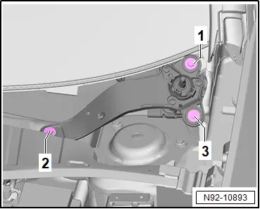
StageComponentSpecified torque/turning further angle1 -1-, -2- and -3- Screw in by hand as far as stop2 -1-, -2- and -3- 8 N·m

Moving wipers to service position

Moving wipers to service position

NOTICE

The bonnet can be damaged if the wipers are allowed to run back to the park position.

– Never move the vehicle when the wiper arms are lifted up off the windscreen.

NOTICE

Risk of damage if frozen wiper blades are moved.

– Allow wiper blades to thaw before operating wipers.

Note

Wiper motor only runs when bonnet is completely closed.

– Switch ignition on and then off again.

– Press wiper lever to touch wipe position within 10 seconds.

Removing and installing wiper blade

Removing and installing wiper blade

NOTICE

Risk of damage to windscreen.

– Make sure wiper arm does not drop back into position unintentionally.

NOTICE

Risk of damage to wiper blade.

– When lifting wiper blades off windscreen, only take hold of them in vicinity of wiper blade mounting.

– Avoid bending wiper arm and wiper blade.

Removing

– → Rep. gr.92; Move wipers to service position.

– Lift wiper arm off windscreen.

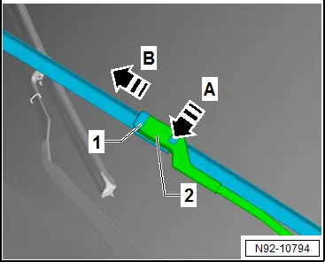
– Release retaining clip in direction of -arrow A-.

– Pull wiper blade -1- off wiper arm -2- in direction of -arrow B-.
Installing

Installation is carried out in reverse order; note the following:

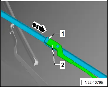
– Insert wiper blade -1- into wiper arm -2- in direction of -arrow-, keeping it parallel.

– Slide wiper blade -1- into wiper arm -2- until retaining clip engages audibly.
– Operate touch wipe function to leave service position.

Removing and installing wiper arms

Removing and installing wiper arms

Special tools and workshop equipment required

♦ puller -T10369/5-

Removal and installation are described for a left-hand drive vehicle as an example.

Removing

– → Rep. gr.92; Move wipers to service position.

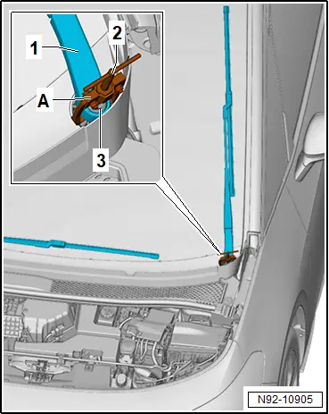
– Using suitable screwdriver, lever caps -3- off wiper arms -1-.

– Loosen nuts -2- a few turns.

– Move wiper arms -1- to upper turning point.
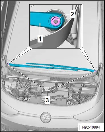
– Mount puller -T10369/5- -A- on wiper arm -1-.

– Position thrust piece -3- on wiper motor shaft.

– Turn spindle -2- clockwise until wiper arm -1- is pulled off wiper motor shaft.

– Remove puller -A- from wiper arm -1-.

– Unscrew nut.

– Remove wiper arm -1-.
Installing

Install in reverse order of removal, observing the following:

– Switch on ignition.

– Actuate “flick wipe” function and allow wiper arms to move to their end position.

– Fit both wiper arms in approximate park positions on wiper arm shafts.

– Loosely screw on nuts of wiper arms.

– → Rep. gr.92; Adjust wiper arms.

Tightening torques

♦ → Rep. gr.92; Assembly overview – windscreen wiper system

Adjusting wiper arms

Adjusting wiper arms

Procedure

The adjustment procedure is described for a left-hand drive vehicle as an example.

– Activate vehicle’s drive system.

– Actuate “flick wipe” function and allow wiper arms to move to their end position.

– Deactivate vehicle’s drive system.

– Loosen wiper arms → Rep. gr.92; Removing and installing wiper arms.

– Adjust wiper arms.

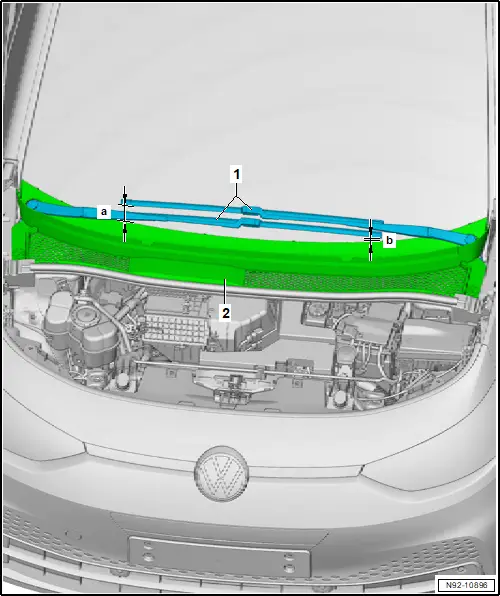
Driver side

Distance -a- between end of wiper blade and plenum chamber cover -2- at bottom edge of windscreen must be 70 mm.

– Adjust wiper blade park position by repositioning wiper arm -1- if necessary.
All vehicles (continued)

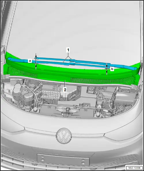
Passenger side

Distance -a- between end of wiper blade and plenum chamber cover -2- at bottom edge of windscreen must be 15 mm.

– Adjust wiper blade park position by repositioning wiper arm -1- if necessary.
All vehicles (continued)

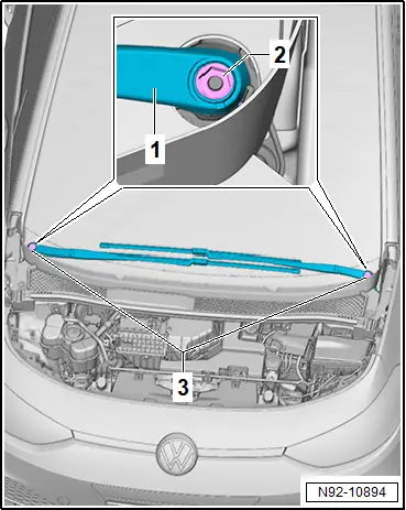
– Tighten nuts of wiper arms.

– Activate vehicle’s drive system.

– Actuate “flick wipe” function and allow wiper arms to move to their end position.

– Deactivate vehicle’s drive system.

– Check wiper arm adjustment again, and correct it if necessary.

– Press caps -3- onto wiper arms.
Tightening torques

♦ → Rep. gr.92; Assembly overview – windscreen wiper system

Removing and installing wiper motor

Removing and installing wiper motor

NOTICE

Risk of malfunction of the wiper system.

– When the wiper motor is renewed, only wiper motors of the same software version may be used.

Driver side windscreen wiper motor -V216- and front passenger side windscreen wiper motor -V217- will henceforth be referred to as “wiper motor”.

Removal and installation are described for a left-hand drive vehicle as an example.

Removing

If renewing wiper motor:

– Carry out required function/functions using → Vehicle diagnostic tester → Rep. gr.00; Access to diagnoses.

Continued

– Remove plenum chamber cover → General body repairs, exterior; Rep. gr.50; Plenum chamber bulkhead; Removing and installing plenum chamber cover.

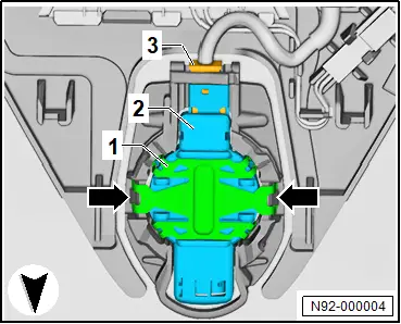
– Unscrew bolts -2-.

– Disconnect electrical connector -3-.

– If fitted, disconnect connector of electronic damping control.

– Remove rear window wiper motor -1-.

Installing

Install in the reverse order of removal, observing the following:

If wiper motor has been renewed:

– Carry out required function/functions using → Vehicle diagnostic tester → Rep. gr.00; Access to diagnoses.

Continued

Tightening torques

♦ → Rep. gr.92; Adjusting wiper arms

♦ → Rep. gr.92; Assembly overview – windscreen wiper system

Removing and installing rain and light sensor [G397]

Removing and installing rain and light sensor [G397]

Rain and light sensor -G397- with humidity sender for air conditioning system -G260- and sunlight penetration photosensor -G107- are referred to hereafter as sensor.

Removing

If sensor is renewed:

– Carry out required function/functions using → Vehicle diagnostic tester → Rep. gr.00; Access to diagnoses.

Continued

– Remove interior mirror → General body repairs, interior; Rep. gr.68; Interior mirror; Removing and installing interior mirror.

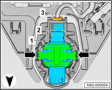
– Disconnect electrical connector -3-.

– Release fasteners -arrows-.

NOTICE

Risk of damage to the coupling pad if removal is done too abruptly.

– Wait at least 1 minute to allow the coupling pad to decompress.

– Starting from top, carefully remove sensor -2- from retaining plate for interior mirror.

– Remove sensor -2-.
Installing

Install in the reverse order of removal, observing the following:

– Thoroughly clean windscreen in area of interior mirror retaining plate.

Removed sensor:

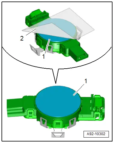
– Pull off coupling pad -2- in direction of -arrow-.

NOTICE

Risk of damage to silicone layer of rain and light sensor.

– Clean the surface of the rain and light sensor thoroughly.

– Clean sensor -1- by sticking and then peeling off one or several commercially available adhesive strips on bonding surface of sensor -1-.

– Clean bonding surface of sensor -1- with lint-free cleaning cloth.

– Pull silicone paper -1- off coupling pad -3-.

Important

● Protective film -2- must remain on coupling pad -3-.
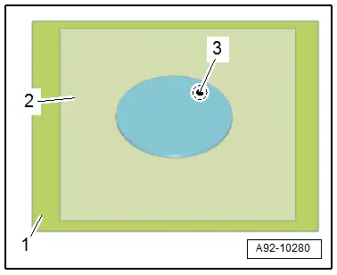
– With aid of protective film -1-, position coupling pad -2- centrally on sensor -3-.

– Press on coupling pad -2- with protective film -1- free of bubbles.

– Pull off protective film -2-.
All vehicles (continued)

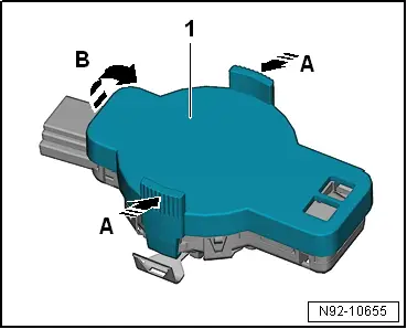
New sensor:

– Press grip in direction of arrows -A-.

– Remove protective cap -1- in direction of -arrow B-.
All vehicles (continued)

– Insert sensor -2- in retaining plate for interior mirror.

NOTICE

Malfunctions of rain and light sensor.

– If the contact surface is not free of bubbles after 10 minutes, the rain and light sensor must be removed and inserted anew.

Important

● Retaining clip -1- must engage audibly.

– Press on retaining clip.

– Connect electrical connector -3-.
If sensor has been renewed:

– Carry out required function/functions using → Vehicle diagnostic tester → Rep. gr.00; Access to diagnoses.