Lights, lamps, switches outside. LED matrix headlight
- Assembly overview – headlight
- Removing and installing headlight
- Installing repair kit for headlight housing
- Removing and installing headlight range control motor [V48]/[V49]
- Removing and installing LED module for daytime running light and side light [L176]/[L177]
- Removing and installing output module 1 for LED headlight [A27]/[A31]
- Removing and installing light conductor for contour lighting in radiator grille [L362]/[L363]
- Removing and installing headlight fan [V407]/[V408]
Assembly overview – headlight
Assembly overview – headlight
Overview shown for the left side of the vehicle as an example
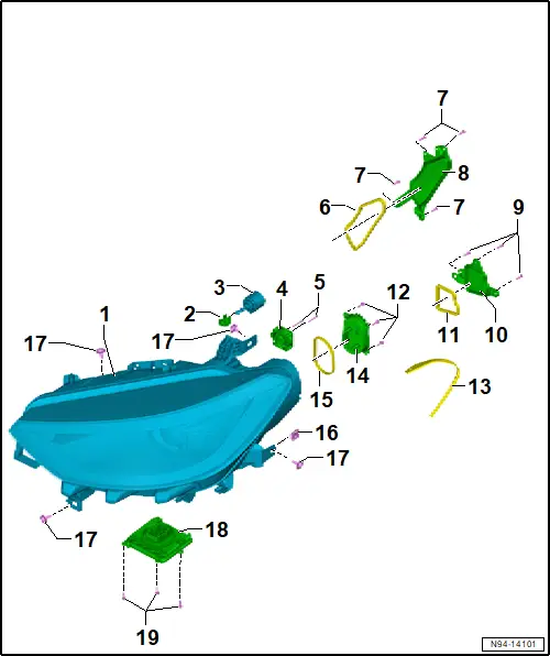
1 - Front left headlight -MX1-/front right headlight -MX2-
❏ Adjusting headlight → Booklet; Descriptions of work
❏ → Rep. gr.94; Removing and installing headlight
2 - Support
❏ For headlight range control motor
3 - Left headlight range control motor -V48-/right headlight range control motor -V49-
❏ → Rep. gr.94; Removing and installing headlight range control motor [V48]/[V49]
4 - Left headlight fan -V407-/right headlight fan -V408-
❏ → Rep. gr.94; Removing and installing headlight fan [V407]/[V408]
5 - Bolt
❏ Qty. 2
❏ 1,5 N·m
6 - Gasket
7 - Bolt
❏ To be used in event of repairs
❏ Qty. 4
❏ 1,5 N·m
8 - Housing cover
❏ To be used in event of repairs
9 - Bolt
❏ To be used in event of repairs
❏ Qty. 4
❏ 1,5 N·m
10 - Housing cover
❏ To be used in event of repairs
❏ For headlight fan
11 - Gasket
❏ For housing cover
12 - Bolt
❏ Qty. 3
❏ 1,5 N·m
13 - Gasket
14 - Left LED module for daytime running light and side light -L176-/right LED module for daytime running light and side light -L177-
❏ With front left turn signal bulb -M5-/front right turn signal bulb -M7-
❏ → Rep. gr.94; Removing and installing LED module for daytime running light and side light [L176]/[L177]
15 - Gasket
❏ For left LED module for daytime running light and side light [L176]/[L177]
16 - Speed nut
17 - Bolt
❏ Qty. 4
❏ 4,5 N·m
18 - Output module 1 for left LED headlight -A31-/output module 1 for right LED headlight -A27-
❏ → Rep. gr.94; Removing and installing output module 1 for LED headlight [A27]/[A31]
19 - Bolt
❏ Qty. 3
❏ 1,5 N·m
Removing and installing headlight
Removing and installing headlight
Front left headlight -MX1- and front right headlight -MX2- are referred to hereafter as headlight.
Removing
– Remove bumper cover → General body repairs, exterior; Rep. gr.63; Front bumper; Removing and installing bumper cover.
– Remove bracket for control unit for break-in protection.
Headlight on driver side
– Pull off Bowden cable coupling from headlight → General body repairs, exterior; Rep. gr.55; Bonnet; Removing and installing Bowden cable.
All vehicles (continued)
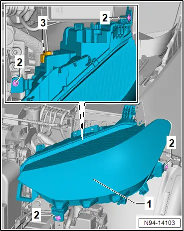
– Unscrew bolts -2-.
– Disconnect electrical connector -3-.
– Remove headlight -1-.
Installing
Install in the reverse order of removal, observing the following:
– Push headlight into guide mountings.
– Check headlight adjustment and adjust headlights → Booklet; Descriptions of work.
Tightening torques
♦ → Rep. gr.94; Assembly overview – headlight
ComponentSpecified torqueBolts of bracket for control unit for break-in protection 2 N·m
Installing repair kit for headlight housing
Installing repair kit for headlight housing
Front left headlight -MX1- and front right headlight -MX2- are referred to hereafter as headlight.
The description focuses on one headlight version for demonstration purposes.
Note
Different repair kits are available → Electronic parts catalogue (ETKA).
Removing
– Remove headlight with damaged retaining tab → Rep. gr.94; Removing and installing headlight.
– Remove remains of damaged retaining tab.
Installing
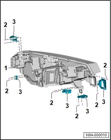
– Fit retaining tab -3- of repair kit to headlight -1-.
– Tighten bolts -2-.
Further installation is carried out in reverse order of removal, observing the following:
– Install headlight and align it flush to body contour.
– Check headlight adjustment and adjust headlights → Booklet; Descriptions of work.
Tightening torques
ComponentSpecified torqueBolts securing repair tab1.5 N·m
Removing and installing headlight range control motor [V48]/[V49]
Removing and installing headlight range control motor [V48]/[V49]
Special tools and workshop equipment required
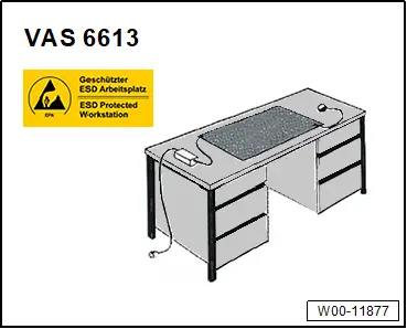
♦ ESD workplace -VAS 6613-
The front left headlight -MX1- and front right headlight -MX2- will henceforth be referred to as “headlight”.
The left headlight range control motor -V48- and right headlight range control motor -V49- will henceforth be referred to as “control motor”.
Removal and installation are described for left-hand side of vehicle as an example.
Removing
– Remove headlight → Rep. gr.94; Removing and installing headlight.
 NOTICE
Risk of damage to electrical components.
Electrostatic charge may damage electrical components.
– Work on electrical components must always be carried out at an ESD workplace.
– Place headlight onto ESD workplace -VAS 6613-.
– Turn height adjustment screws of headlight to stop towards right.
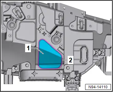
– Use a hammer to carefully release housing cover -1- along predetermined break line -2-.
– Remove housing cover -1- from headlight.
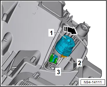
– Release control motor -1-:
♦ On left headlight, turn in direction of -arrow-.
♦ for right headlight, turn in opposite direction of -arrow-.
– Swing left headlight range control motor -1- downwards so that the ball head is pushed upwards out of ball head mounting -3-.
– Pull control motor -1- towards rear out of headlight until electrical connector -2- is accessible.
– Disconnect connector -2-.
– Remove control motor -1-.
Installing
Install in the reverse order of removal, observing the following:
– Pull ball head mounting towards rear.
– Engage ball head on control motor into ball head mounting in headlight.
 NOTICE
Risk of destroying headlight due to ingress of water.
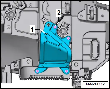
– When installing the housing cover -1-, make sure that the seal is correctly seated.
Note
A new housing cover -1- must be used only, if the repair is carried out for the first time.
– Fit housing cover -1- on headlight.
– Tighten bolts -2-.
– Check headlight adjustment and adjust headlights → Booklet; Descriptions of work.
Tightening torques
♦ → Rep. gr.94; Assembly overview – headlight
Removing and installing LED module for daytime running light and side light [L176]/[L177]
Removing and installing LED module for daytime running light and side light [L176]/[L177]
Special tools and workshop equipment required
♦ ESD workplace -VAS 6613-
Front left headlight -MX1- and front right headlight -MX2- are referred to hereafter as headlight.
Left LED module for daytime running light and side light -L176- and right LED module for daytime running light and side light -L177- are referred to hereafter as LED module for daytime running light.
Removal and installation are described for the left vehicle side as an example.
Removing
– Remove headlight → Rep. gr.94; Removing and installing headlight.
 NOTICE
Risk of damage to electrical components.
Electrostatic charge may damage electrical components.
– Work on electrical components must always be carried out at an ESD workplace.
– Place headlight on ESD workplace -VAS 6613-.
– Unscrew bolts -2-.
– Guide LED module for daytime running light -1- out of headlight housing.
– Disconnect electrical connector.
– Remove LED module for daytime running -1-.

Installing
Install in the reverse order of removal, observing the following:
 NOTICE
Risk of destroying headlight due to ingress of water.
– Check seal between LED module for daytime running and headlight for damage.
– Ensure proper seating of gasket.
– Check headlight settings and adjust headlights if necessary → Booklet53.1; Descriptions of work.
Tightening torques
♦ → Rep. gr.94; Assembly overview – headlight
Removing and installing output module 1 for LED headlight [A27]/[A31]
Removing and installing output module 1 for LED headlight [A27]/[A31]
Special tools and workshop equipment required
♦ ESD workplace -VAS 6613-
Front left headlight -MX1- and front right headlight -MX2- are referred to hereafter as headlight.
Output module 1 for left LED headlight -A31- and output module 1 for right LED headlight -A27- are referred to hereafter as output module.
Removing
If output module is renewed:
– Carry out required function/functions using → Vehicle diagnostic tester → Rep. gr.00; Access to diagnoses.
Continued
– Remove headlight → Rep. gr.94; Removing and installing headlight.
 NOTICE
Risk of damage to electrical components.
Electrostatic charge may damage electrical components.
– Work on electrical components must always be carried out at an ESD workplace.
– Place headlight on ESD workplace -VAS 6613-.
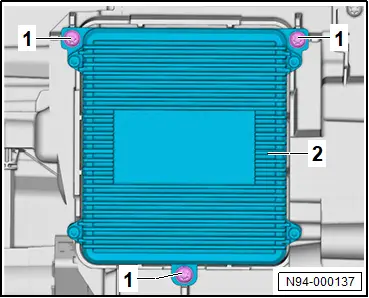
– Unscrew bolts -1-.
– Pull off output module -2- from headlight.
Installing
Install in the reverse order of removal, observing the following:
 NOTICE
Risk of destroying headlight due to ingress of water.
– Check seal between output module and headlight for damage.
– Make sure seal is properly seated.
– Check headlight settings and adjust headlights if necessary → Booklet53.1; Descriptions of work.
Tightening torques
♦ → Rep. gr.94; Assembly overview – headlight
Removing and installing light conductor for contour lighting in radiator grille [L362]/[L363]
Removing and installing light conductor for contour lighting in radiator grille [L362]/[L363]
Light conductor for contour lighting in radiator grille, front left -L363- and light conductor for contour lighting in radiator grille, front right -L362- are referred to hereafter as “light conductor”.
Removing
– Remove bumper cover → General body repairs, exterior; Rep. gr.63; Front bumper; Removing and installing bumper cover.
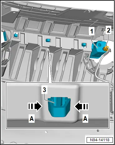
– Disconnect electrical connector -2-.
– Release retaining clips -3- in direction of -arrow A-.
– Pull out light conductor -1-.
Installing
Install in reverse order of removal, observing the following:
Removing and installing headlight fan [V407]/[V408]
Removing and installing headlight fan [V407]/[V408]
Special tools and workshop equipment required
♦ ESD workplace -VAS 6613-
Front left headlight -MX1- and front right headlight -MX2- will henceforth be referred to as “headlight”.
Left headlight fan -V407- and right headlight fan -V408- will henceforth be referred to as “fan”.
Removal and installation are described for the left vehicle side as an example.
Removing
– Remove headlight → Rep. gr.94; Removing and installing headlight.
 NOTICE
Risk of damage to electrical components.
Electrostatic charge may damage electrical components.
– Work on electrical components must always be carried out at an ESD workplace.
– Place headlight on ESD workplace -VAS 6613-.
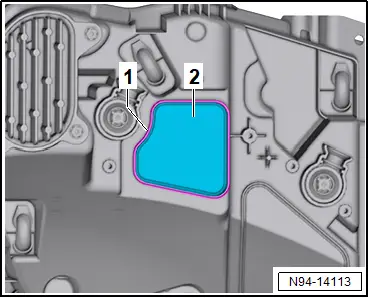
– Use a hammer to carefully release housing cover -2- along predetermined break line -1-.
– Remove housing cover -2- from headlight.
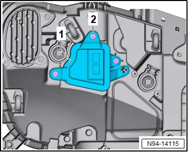
– Unscrew bolts -3-.
– Disconnect electrical connector -2-.
– Remove fan -1-.

Installing
Install in reverse order of removal, observing the following:
 NOTICE
Risk of destroying headlight due to ingress of water.
– When installing the housing cover -1-, make sure that the seal is correctly seated.
Note
A new housing cover -1- must be used only if the repair is carried out for the first time.
– Fit housing cover -1- on headlight.
– Tighten bolts -2-.
– Check headlight adjustment and adjust headlights → Booklet; Descriptions of work.
Tightening torques
♦ → Rep. gr.94; Assembly overview – headlight