Infotainment. Componentscontrol units
- Removing and installing control unit for front display and information control panel [J685]
- Removing and installing control unit 1 for information electronics [J794]
- Removing and installing bracket for control unit 1 for information electronics [J794]
- Removing and installing bass loudspeaker
- Removing and installing subwoofer [R211]
- Removing and installing subwoofer [R211], spare wheel well
- Removing and installing aerial module
- Removing and installing frequency modulation (FM) frequency filters [R178]/[R179]
- Removing and installing roof aerial [RX5]
- Removing and installing LTE aerial
- Removing and installing internet access control unit [J666]
- Removing and installing data transmission aerial [R180]
- Removing and installing charging unit 1 for mobile devices [J1146]
- Removing and installing aerial amplifier for mobile telephone [R86]
- Removing and installing multifunction buttons [E440]/[E441]
- Removing and installing control unit for steering wheel contact detection [J1158]
- Removing and installing loudspeaker for emergency call module [R335]
- Removing and installing emergency battery, telematics [A16]
- Removing and installing USB connection 1 [U41]
- Removing and installing USB charging socket 1 [U37]
- Removing and installing digital sound package control unit [J525]
- Removing and installing retainer for digital sound package control unit [J525]
Removing and installing control unit for front display and information control panel [J685]
Removing and installing control unit for front display and information control panel [J685]
Removing
The display unit for front information display and operating unit control unit -J685- will henceforth be referred to as “display and operating unit control unit”.
– Remove information electronics cover → General body repairs, interior; Rep. gr.68; Compartments/covers; Removing and installing information electronics cover.
– Unscrew bolts -1-, and pull out display and operating unit control unit.
– Disconnect electrical connectors.

Installing
Install in the reverse order of removal, observing the following:
 NOTICE
Risk of damage to the display due to excessive pressure.
– When inserting the unit, do not apply pressure to the display.
– Handle the display and operating unit control unit with care.
Tightening torques
ComponentSpecified torqueBolts on dash panel4 Nm
Removing and installing control unit 1 for information electronics [J794]
Removing and installing control unit 1 for information electronics [J794]
Removing
The control unit 1 for information electronics -J794- will henceforth be referred to as “information electronics control unit”.
Removal and installation are described for a left-hand drive vehicle as an example.
If the control unit for information electronics is renewed, perform the test plan for the renewal of the control unit:
– Carry out function “Renew control unit for information electronics” using → Vehicle diagnostic tester → Rep. gr.00; Access to diagnoses.
Continued
– Remove glove compartment cover → General body repairs, interior; Rep. gr.68; Compartments/covers; Removing and installing glove compartment cover.
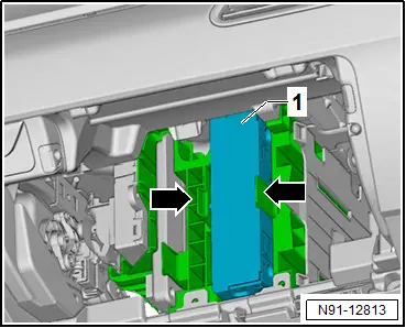
– Release locking devices -arrows-, and pull out information electronics control unit -1- while at the same time swivelling it downwards.
– Disconnect electrical connectors.
Installing
Install in the reverse order of removal, observing the following:
Important
● The information electronics control unit must engage audibly.
If the control unit for information electronics has been renewed, conclude the test plan for the renewal of the control unit:
– Conclude function “Renew control unit for information electronics” using → Vehicle diagnostic tester → Rep. gr.00; Access to diagnoses.
Removing and installing bracket for control unit 1 for information electronics [J794]
Removing and installing bracket for control unit 1 for information electronics [J794]
Removing
The bracket for the control unit 1 for information electronics -J794- will henceforth be referred to as “bracket”.
Removal and installation are described for a left-hand drive vehicle as an example.
– Remove footwell vent on front passenger side → Heating, air conditioning; Rep. gr.87; Air duct; Removing and installing footwell vent on front passenger side.
– Remove dash panel trim on front passenger side → General body repairs, interior; Rep. gr.68; Compartments/covers; Removing and installing dash panel trim on front passenger side.
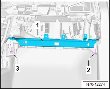
– Unscrew bolts -2- and -3-.
– Detach strut -1-.
– Remove control unit 1 for information electronics -J794- → Rep. gr.91; Removing and installing control unit 1 for information electronics [J794].
– Remove heater and air conditioning system control unit -J979- → Heating, air conditioning system; Rep. gr.87; Other control components; Removing and installing heater and air conditioning system control unit [J979].
– Remove data bus diagnostic interface -J533- → Electrical system; Rep. gr.97; Control units; Removing and installing data bus diagnostic interface [J533].
– Loosen fan for control unit -V274-, and lay it aside with electrical wiring still connected → Electrical system; Rep. gr.97; Control units; Removing and installing fan for control unit [V274].
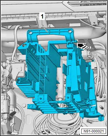
– Pull out bracket -1- in direction of -arrow-, and detach it.
Installing
Install in the reverse order of removal, observing the following:
Tightening torques
♦ → General body repairs, interior; Rep. gr.70; Central tube for dash panel; Assembly overview – central tube for dash panel
Removing and installing bass loudspeaker
Removing and installing bass loudspeaker
Special tools and workshop equipment required
♦ Drill, commercially available
♦ pop rivet pliers, commercially available
♦ suitable drill bit approx. 4 mm, commercially available
Removing
Front loudspeakers:
– Remove front door trim → General body repairs, interior; Rep. gr.70; Front door trims; Removing and installing front door trim.
All vehicles (continued)
Rear loudspeakers:
4-door model
– Remove rear door trim → General body repairs, interior; Rep. gr.70; Rear door trims; Removing and installing rear door trim.
2-door model
– Remove side trim → General body repairs, interior; Rep. gr.70; Trims, interior; Removing and installing side trim.
All vehicles (continued)
– Disconnect electrical connector -2-.

 CAUTION
Risk of eye injuries due to metal swarf.
Eye irritation and injury possible.
– Put on safety goggles.
 NOTICE
Corrosion damage due to swarf and damaged paintwork
– Completely remove swarf from the door, and immediately rectify any paintwork damage caused.
– Drill out pop rivets -3-, and remove loudspeaker -1-.
Installing
Install in reverse order of removal, observing the following:
Important
● Only secure the loudspeaker using the specified pop rivets → Electronic parts catalogue (ETKA).
Removing and installing subwoofer [R211]
Removing and installing subwoofer [R211]
The subwoofer -R211- will henceforth be referred to as “subwoofer”.
Removing
– Remove luggage compartment floor.
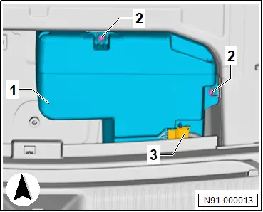
– Disconnect electrical connector -3-.
– Unscrew bolts -2-.
– Lift out subwoofer -1-.
Installing
Install in the reverse order of removal, observing the following:
ComponentSpecified torqueBolts on subwoofer8 Nm
Removing and installing subwoofer [R211], spare wheel well
Removing and installing subwoofer [R211], spare wheel well
The subwoofer -R211- will henceforth be referred to as “subwoofer”.
Removing
– Remove luggage compartment floor.
– Disconnect electrical connector -2-.
– Unscrew nut -3-.
– Lift out subwoofer -1-.
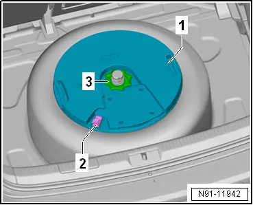
Installing
Install in reverse order of removal.
ComponentSpecified torqueNut -3- on subwoofer6 Nm
Removing and installing aerial module
Removing and installing aerial module
Removing
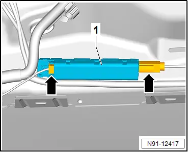
The radio aerial 2 -R93-, aerial -R11- and digital radio aerial -R183- will henceforth be referred to as “aerial module”.
Removal and installation are described for the left vehicle side as an example.
– Remove upper rear lid trim → General body repairs, interior; Rep. gr.70; Luggage compartment trims; Removing and installing upper rear lid trim.
– Disconnect electrical connectors -arrows-.
– Unscrew bolt -2-.
– Pull off aerial module -1- in direction of -arrow-.
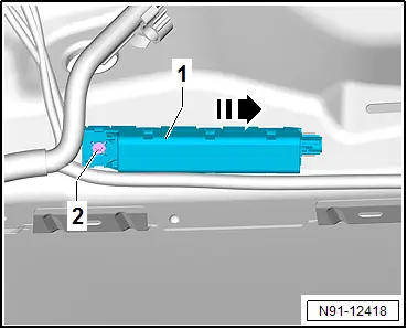
Installing
Install in reverse order of removal, observing the following:
Tightening torques
ComponentSpecified torqueBolt to rear lid2 Nm
Removing and installing frequency modulation (FM) frequency filters [R178]/[R179]
Removing and installing frequency modulation (FM) frequency filters [R178]/[R179]
The frequency modulation (FM) frequency filter in negative wire -R178- and frequency modulation (FM) frequency filter in positive wire -R179- will henceforth be referred to as “frequency filter”.
Removal and installation are described for the left vehicle side as an example.
Removing
– Remove rear lid side trim → General body repairs, interior; Rep. gr.70; Luggage compartment trims; Removing and installing rear lid side trim.
– Disconnect electrical connectors -2-.
– Using commercially available plastic wedge, carefully lever out frequency filter -1-, and remove it.
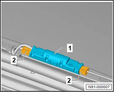
Installing
Install in the reverse order of removal, observing the following:
Important
● The frequency filter must engage audibly.
Removing and installing roof aerial [RX5]
Removing and installing roof aerial [RX5]
The roof aerial -RX5- will henceforth be referred to as “roof aerial”.
Removing
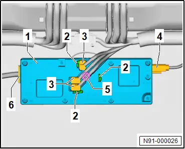
– Move clear internet access control unit -J666- → Rep. gr.91; Removing and installing internet access control unit [J666].
– Disconnect electrical connectors -3-.
– Loosen bolt -5-.
– Detach internet access control unit -J666- -1-, and put it aside with electrical wiring -4- and -6- still connected.

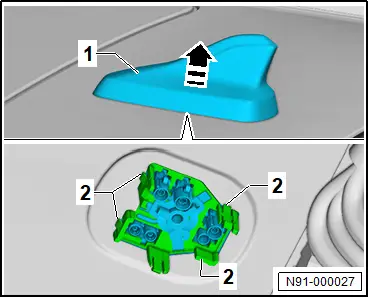
– Release locking devices -2-.
– Remove roof aerial -1- in direction of -arrow-.
Installing
Install in the reverse order of removal, observing the following:
– Press on roof aerial until it can be heard to engage.
Removing and installing LTE aerial
Removing and installing LTE aerial
The LTE aerial 1 -R297- and LTE aerial 2 -R306- will henceforth be referred to as “LTE aerial”.
Removing
– Remove bumper cover → General body repairs, exterior; Rep. gr.63; Rear bumper; Removing and installing bumper cover.
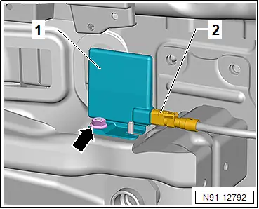
– Disconnect electrical connector -2-.
– Unscrew nut -arrow-, and detach LTE aerial -1-.
Installing
Install in the reverse order of removal, observing the following:
Tightening torques
ComponentSpecified torqueNut to carrier6 Nm
Removing and installing internet access control unit [J666]
Removing and installing internet access control unit [J666]
The internet access control unit -J666- will henceforth be referred to as “internet access control unit”.
Removing
– Detach moulded headliner, and place it onto head restraints → General body repairs, interior; Rep. gr.70; Roof trims; Removing and installing moulded headliner.
– Disconnect electrical connectors -3-, -4- and -6-.
– Loosen bolt -5-.
– Release locking device -2-, and detach internet access control unit -1-.
Installing
Install in reverse order of removal, observing the following:
Tightening torques
ComponentSpecified torqueBolt on roof aerial9 Nm
Removing and installing data transmission aerial [R180]
Removing and installing data transmission aerial [R180]
The data transmission aerial -R180- will henceforth be referred to as “data transmission aerial”.
Removing
– Remove lower cover → General body repairs, interior; Rep. gr.68; Interior mirror; Removing and installing interior mirror.
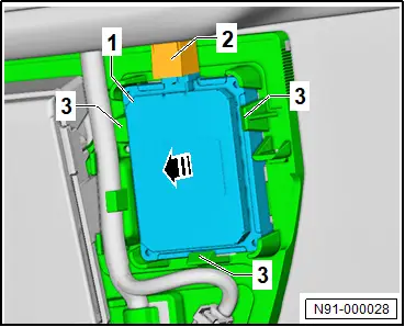
– Release locking devices -3-, and detach data transmission aerial -1- in direction of -arrow-.
– Disconnect electrical connector -2-.
Installing
Install in reverse order of removal.
Removing and installing charging unit 1 for mobile devices [J1146]
Removing and installing charging unit 1 for mobile devices [J1146]
Charging unit 1 for mobile devices -J1146- is referred to hereafter as charging unit.
Removing
– Remove lining mat from centre console storage compartment.
 NOTICE
Risk of damage to component surfaces when sharp-edged levers are used
– Mask off component in visible area using commercially available adhesive tape before using a levering tool.
– Release locking devices -2- and remove charging unit -1-.
– Disconnect electrical connector.
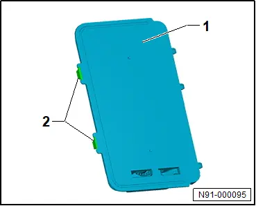
Installing
Install in reverse order of removal.
Removing and installing aerial amplifier for mobile telephone [R86]
Removing and installing aerial amplifier for mobile telephone [R86]
Removing
– Remove parking aid control unit -J446- → Driver assist systems; Rep. gr.98; Senders/sensors/control units; Removing and installing parking aid control unit [J446].
– Unscrew nut -2-.
– Unclip bracket -1- -arrows- and remove.

– Disconnect electrical connector -3-.
– Unclip aerial amplifier for mobile telephone -R86- -1- from bracket -2- -arrow- and remove.

Installing
Install in reverse order of removal, observing the following:
Tightening torques
ComponentSpecified torqueNut to body2.5 N·m
Removing and installing multifunction buttons [E440]/[E441]
Removing and installing multifunction buttons [E440]/[E441]
The left multifunction buttons in steering wheel -E440- with multifunction steering wheel control unit -J453- and right multifunction buttons in steering wheel -E441- will henceforth be referred to as “multifunction buttons”.
Removing
If the multifunction buttons control unit is renewed, perform the test plan for the renewal of the control unit:
– Carry out function “Renew multifunction buttons” using → Vehicle diagnostic tester → Rep. gr.00; Access to diagnoses.
Continued
– Remove airbag unit with airbag igniter on driver side [N95] → General body repairs, interior; Rep. gr.69; Driver-side airbag; Removing and installing airbag unit with airbag igniter on driver side [N95].
 NOTICE
Risk of damage to the steering wheel.
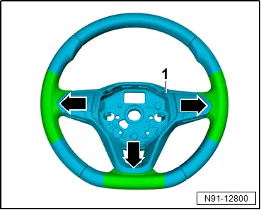
– Mask off the steering wheel at the relevant locations to protect it from damage.
– Mask off steering wheel -1- with adhesive tape in areas indicated by -arrows-.
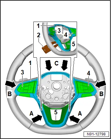
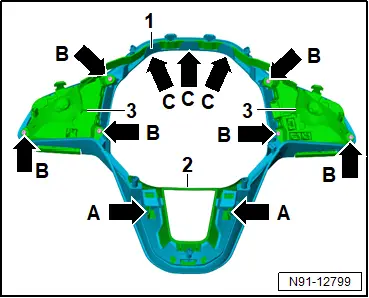
– Using commercially available plastic wedge -2-, unclip trim panel -1- in lower area -arrows-.

– Using commercially available plastic wedge -2-, unclip trim panel -1- successively in indicated areas (-arrows A- through -arrows C-).
– Detach trim -1- together with multifunction buttons -3-, -4- and lower trim -5-.
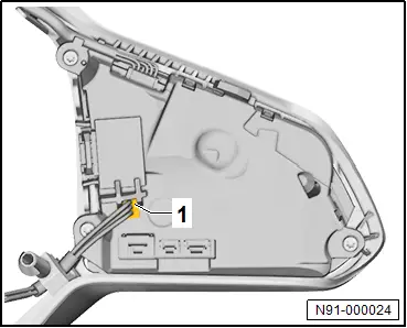
Vehicles with control unit for steering wheel contact detection -J1158-
– Disconnect electrical connector -1-.
All vehicles (continued)
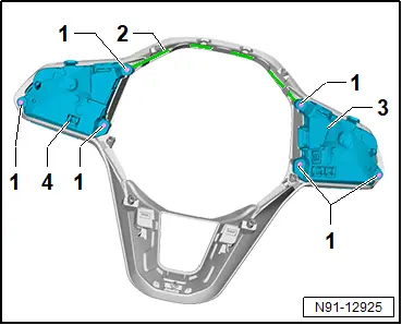
– Unscrew bolts -1-.
– Move clear wiring harness -2-.
– Detach multifunction buttons -3- and -4-.
– Release lower trim panel -2- at fasteners -arrows A-, and remove it.
Installing
Install in the reverse order of removal, observing the following:
– Clip in trim panel from below.
If the multifunction buttons control unit has been renewed, conclude the test plan for the renewal of the control unit:
– Conclude function “Renew multifunction unit control unit” using → Vehicle diagnostic tester → Rep. gr.00; Access to diagnoses.
Continued
Tightening torques
♦ → Rep. gr.91; Assembly overview – multifunction steering wheel
Removing and installing control unit for steering wheel contact detection [J1158]
Removing and installing control unit for steering wheel contact detection [J1158]
The control unit for steering wheel contact detection -J1158- will henceforth be referred to as “control unit”.
Removing
– Remove airbag unit with airbag igniter on driver side [N95] → General body repairs, interior; Rep. gr.69; Driver side airbag; Removing and installing airbag unit with airbag igniter on driver side [N95].
– Remove lower trim panel → Rep. gr.91; Removing and installing multifunction buttons [E440]/[E441].
– Disconnect electrical connectors -1- and -3-.
– Pull out control unit -2- in direction of -arrow-.

Installing
Install in reverse order of removal.
Removing and installing loudspeaker for emergency call module [R335]
Removing and installing loudspeaker for emergency call module [R335]
Emergency call loudspeaker -R335- is referred to hereafter as loudspeaker.
Removing
– Remove loudspeaker trim → General body repairs, interior; Rep. gr.70; Dash panel; Removing and installing loudspeaker trim.
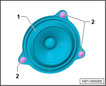
– Unscrew bolts -2-.
– Pull out loudspeaker -1-.
– Disconnect electrical connector.
Installing
Install in the reverse order of removal, observing the following:
Tightening torques
ComponentSpecified torqueBolts securing dash panel1.5 N·m
Removing and installing emergency battery, telematics [A16]
Removing and installing emergency battery, telematics [A16]
The emergency battery, telematics -A16- will henceforth be referred to as “emergency battery”.
Emergency call module control unit and communication unit -J949- is referred to hereafter as control unit.
Removing
If the emergency battery is renewed, perform the test plan for the renewal of the emergency battery.
– Carry out function “Renew emergency battery, telematics” using → Vehicle diagnostic tester → Rep. gr.00; Access to diagnoses.
Continued
– Remove control unit → Rep. gr.91; Removing and installing emergency call module control unit and communication unit [J949].
– Unscrew bolt -2-.
– Remove cover -1-.
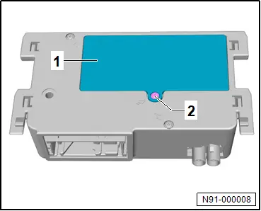
– Disconnect connector -2-.
– Remove emergency battery -1-.

Installing
Install in the reverse order of removal, observing the following:
If the emergency battery was renewed, conclude the test plan for renewal of the emergency battery.
– Conclude function “Renew emergency battery, telematics” using → Vehicle diagnostic tester → Rep. gr.00; Access to diagnoses.
Continued
Tightening torques
ComponentSpecified torqueBolt to emergency call module control unit1.5 N·m
Removing and installing USB connection 1 [U41]
Removing and installing USB connection 1 [U41]
Removing
– Remove centre console → General body repairs, interior; Rep. gr.68; Centre console; Removing and installing centre console.
– Disconnect electrical connector.
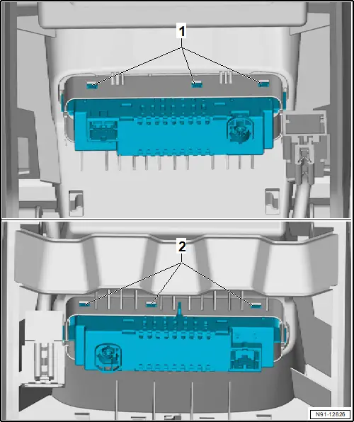
– Release locking devices -1- and -2-, and pull out USB connection 1 -U41-.
Installing
Install in the reverse order of removal, observing the following:
Important
● The USB connection 1 -U41- must be heard to engage.
Removing and installing USB charging socket 1 [U37]
Removing and installing USB charging socket 1 [U37]
Removing
– Remove trim at rear of centre console → General body repairs, interior; Rep. gr.68; Centre console; Removing and installing rear centre console trim.
– Disconnect electrical connector.
– Release locking devices -arrows-.
– Press USB charging socket 1 -U37- -1- out of rear centre console trim -2- in direction of -arrow A-.

Installing
Install in the reverse order of removal, observing the following:
Important
● USB charging socket 1 -U37- must be heard to engage.
Removing and installing digital sound package control unit [J525]
Removing and installing digital sound package control unit [J525]
Removing
The digital sound package control unit -J525- will henceforth be referred to as “control unit”.
If the digital sound package control unit is renewed, perform the test plan for the renewal of the control unit:
– Carry out function “Renew digital sound package control unit” using → Vehicle diagnostic tester → Rep. gr.00; Access to diagnoses.
Continued
– Remove left luggage compartment side trim → General body repairs, interior; Rep. gr.70; Luggage compartment trims; Removing and installing luggage compartment side trim.
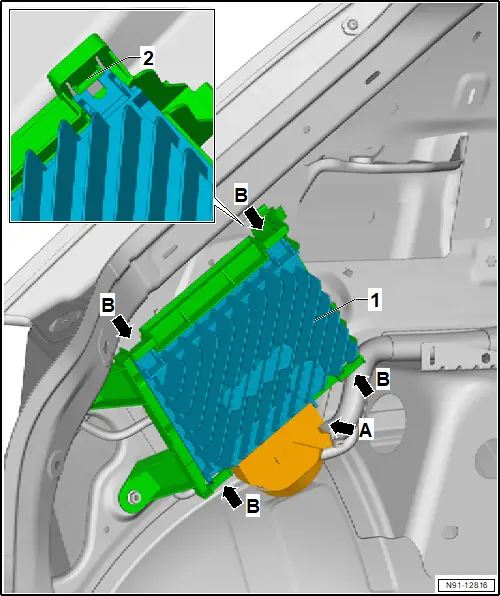
– Disconnect connector -arrow A-.
– Release locking devices -2- at positions indicated by -arrow B-, and remove control unit -1-.
Installing
Install in the reverse order of removal, observing the following:
Important
● The device must be heard to engage in bracket.
If the digital sound package control unit has been renewed, conclude the test plan for the renewal of the control unit:
– Conclude function “Renew digital sound package control unit” using → Vehicle diagnostic tester → Rep. gr.00; Access to diagnoses.
Continued
Tightening torques
Removing and installing retainer for digital sound package control unit [J525]
Removing and installing retainer for digital sound package control unit [J525]
Removing
– Remove digital sound package control unit -J525- → Rep. gr.91; Removing and installing digital sound package control unit [J525].
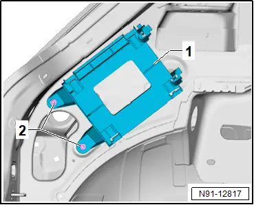
– Unscrew nuts -2-.
– Unclip bracket -1- and remove.
Installing
Install in the reverse order of removal, observing the following:
Important
● Must engage audibly
Tightening torques
ComponentSpecified torqueNut on bracket8 Nm