Hydraulic Lash Adjuster Operation
GENERAL INFORMATION
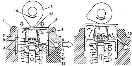
Hydraulic Lash Adjuster Operation Diagram
1. CAMSHAFT LOBE.
2. CYLINDER HEAD.
3. VALVE STEM.
4. OIL CHANNEL.
5. LIFTER WITH HYDRAULIC LASH ADJUSTER.
6. PLUNGER.
7. SLEEVE.
8. CHECK VALVE.
9. CHECK VALVE SPRING.
10. CHECK VALVE CAGE.
11. PLUNGER SPRING.
12. CHAMBER.
13. CHAMBER.
14. SHAFT ROTATION DIRECTION.
15. OIL FLOW
Hydraulic lash adjusters provide virtually zero-lash engagement of the valve train components. The lash adjuster is built into the valve lifter and
is located between the valve stem tip and the lifter base. Oil is supplied to the
hydraulic lash adjusters from the engine lubrication system..
The lash adjuster operates as follows (see figure Hydraulic Lash Adjuster Operation Diagram)..
1) With the valve closed, lifter 5 and sleeve 7 are pressed respectively against the
camshaft lobe 1 and the valve stem tip 3 by spring force
11. Pressure.
oil pressure in chambers A and B is equal, and check valve 8 is pressed against its seat by the spring
9. Clearance.
there is no clearance between the valve and the camshaft lobe..
2) As cam lobe 1 rises onto lifter 5, the lifter acts on plunger 6. Movement of plunger 6 in sleeve 7 causes the pressure in the trapped chamber B to increase..
Under high pressure, small oil leaks occur through the
radial clearance between sleeve 7 and plunger
6. Since the time of cam action on the valve is short, these leaks have practically no effect on the synchronous
movement of lifter 5 and sleeve.
movement of lifter 5 and sleeve.
7. These parts, moving as a single unit, open the valve.
3) During valve closing, the pressure in chamber B becomes lower than the pressure in chamber
A, which is replenished with oil from the lubrication system. Check valve 8
opens and passes oil into chamber B to restore the zero-lash
engagement of the valve train components.
Test yourself
A quick Daewoo Nexia quiz: every answer comes with an explanation and a link to the manual page.