General Description
GENERAL INFORMATION
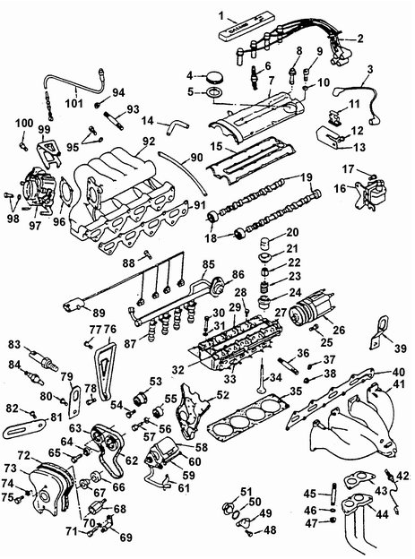
Upper engine components (1.5 L, P4 DOHC)
1. SPARK PLUG COVER.
2. HIGH-TENSION CABLE.
3. CENTRAL HIGH-TENSION CABLE.
4. OIL FILLER CAP.
5. CAP SEAL.
6. SPARK PLUG.
7. VALVE COVER.
8. BOLT M.
9. BOLT.
10. WASHER.
11. SPARK PLUG CABLE HOLDER.
12. BOLT M.
13. SPARK PLUG CABLE BRACKET.
14. BREATHER HOSE.
15. COVER GASKET.
16. IGNITION COIL.
17. PIN.
18. CAMSHAFT FRONT SEAL.
19. CAMSHAFT.
20. VALVE LIFTER WITH HYDRAULIC LASH ADJUSTER.
21. VALVE SPRING RETAINER.
22. VALVE COTTER.
23. VALVE SPRING.
24. VALVE STEM SEAL.
25. BOLT M.
26. IGNITION DISTRIBUTOR.
27. CAMSHAFT BEARING REAR COVER.
28. SCREW M.
29. CAMSHAFT BEARING INTERMEDIATE COVER.
30. CYLINDER HEAD BOLT.
31. WASHER.
32. CAMSHAFT BEARING FRONT COVER.
33. CYLINDER HEAD.
34. VALVE.
35. CYLINDER HEAD GASKET.
36. EXHAUST MANIFOLD STUD.
37. WASHER.
38. NUT.
39. LIFTING EYE.
40. GASKET.
41. EXHAUST PIPE
42. OXYGEN SENSOR
43. EXHAUST PIPE FLANGE GASKET
44. DUAL EXHAUST PIPE
45. EXHAUST PIPE STUD
46. WASHER.
47. NUT
48. BOLT M
49. THERMOSTAT HOUSING
50. SEAL
51. THERMOSTAT
52. TIMING BELT REAR COVER
53. TIMING BELT TENSIONER
54. BOLT M
55. IDLER PULLEY
56. WASHER
57. BOLT M
58. POWER STEERING PUMP
59. BOLT M
60. WASHER
61. PUMP PIPE SEAL
62. TIMING BELT
63. CAMSHAFT TIMING SPROCKET
64. WASHER
65. TIMING SPROCKET BOLT
66. COVER MOUNTING TAPERED BUSHING
67. COVER MOUNTING SPACER BUSHING
68. TIMING BELT COVER STUD
69. BRACKET
70. WASHER
71. BOLT M
72. FRONT TIMING BELT COVER SEAL
73. FRONT TIMING BELT COVER
74. WASHER
75. SCREW M
76. INTAKE MANIFOLD BRACKET
77. SCREW M
78. SCREW M1
79. LIFTING EYE
80. BOLT M
81. GENERATOR BRACKET
82. BOLT M
83. ENGINE COOLANT TEMPERATURE SENSOR
84. ENGINE TEMPERATURE GAUGE SENDER
85. FUEL DISTRIBUTION PIPE
86. FUEL PRESSURE REGULATOR
87. FUEL INJECTOR
88. BOLT M
89. FUEL INJECTION SYSTEM WIRING
90. VACUUM HOSE
91. GASKET
92. INTAKE MANIFOLD
93. INTAKE MANIFOLD STUD
94. NUT M
95. BOLT M8 WITH WASHER
96. GASKET
97. THROTTLE BODY
98. BOLT M8 WITH WASHER
99. THROTTLE CABLE SHEATH BRACKET
100. BOLT M
101. THROTTLE CABLE IN SHEATH

Lower Engine Assembly (1.5 L, P4 DOHC)
111. OIL LEVEL DIPSTICK
112. GUIDE TUBE
113. CYLINDER HEAD BUSHING
114. CYLINDER BLOCK
115. CLUTCH HOUSING BUSHING
116. PLUG
117. OIL FILTER
118. OIL FILTER BUSHING
119. BUSHING
120. PLUG
121. PLUG BUSHING
122. BOLT WITH WASHER
123. CLUTCH COVER
124. CLUTCH DRIVEN DISC
125. BOLT
126. FLYWHEEL
127. REAR CRANKSHAFT SEAL
128. CRANKSHAFT
129. MAIN BEARING INSERTS
130. Center main bearing thrust washer.
131. Rear main bearing seal retainer.
132. Bolt.
133. Oil pan gasket.
134. Oil pan.
135. Drain plug.
136. Drain plug gasket.
137. Bolt.
138. Woodruff key.
139. Oil pump inlet pipe bracket and bolt.
140. Oil pump inlet pipe.
141. Bolt M.
142. Oil pump inlet pipe seal.
143. Oil pressure relief valve plug (M20x1.5).
144. Oil pressure relief valve seal.
145. Oil pressure relief valve spring.
146. Oil pressure relief valve plunger.
147. Oil pump.
148. Ball.
149. Oil pump bypass valve.
150. Seal.
151. Oil pressure warning switch.
152. Crankshaft front oil seal.
153. Crankshaft sprocket.
154. Cover seal.
155. Cover.
156. Bolt.
157. Pulley.
158. Washer.
159. Pulley bolt.
160. Bolt M.
161. Oil pump rotor.
162. Oil pump drive gear.
163. Oil pump cover.
164. Countersunk head screw.
165. Oil pump gasket.
166. Water pump bolt.
167. Water pump.
168. Water pump seal.
169. Plug.
170. Coolant pipe.
171. Connecting rod bolt.
172. Connecting rod cap.
173. Connecting rod bearing set.
174. Piston pin.
175. Piston.
176. Piston ring set.
177. Bolt with washer.
178. Crankcase ventilation tube.
179. Clamp.
180. Crankcase ventilation hose.
181. Bolt M.
182. Starter.
183. Bolt M.
184. Starter bracket.
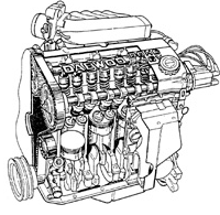
Valve timing mechanism of the engine
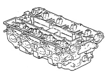
Cylinder head
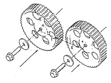
Location of I and E marks when installing timing sprockets
The inline 4-cylinder, 4-stroke gasoline water-cooled engine is equipped with
two camshafts located in the cylinder head. 16.
valves (4 per cylinder) are arranged in a V-configuration. The camshaft drive
is driven from the crankshaft by a timing belt. One of the two camshafts actuates the intake valves, and the other camshaft actuates the exhaust valves. In the
valve drive, hydraulic lash adjusters are installed..
The cylinder block is cast from aluminum alloy and has four cylinders in a row. Cast iron cylinder liners are installed in the cylinder bores..
The cast aluminum alloy cylinder head is of cross-flow design.
Lash adjusters are installed in the valve drive of each
valve.
The forged steel crankshaft is supported by five main bearings with insert bearing shells. Crankpins are located in one plane at 180 degrees. The cast iron camshaft is installed on five bearings in the aluminum
housing located on top of the cylinder head. Rotation of the camshaft
is transmitted from the crankshaft by a timing belt and sprocket,
installed on the front end of the camshaft..
The sprockets installed on both camshafts have identical shape and are marked with letters I and E (respectively for the shaft controlling the
intake valves, and for the shaft controlling the exhaust valves)..
Warning.
New camshafts installed on the intake and exhaust
valves are interchangeable. However, used camshafts are not
interchangeable..
Pistons are made of aluminum alloy. Each piston has two
compression rings and one oil control ring. To reduce piston pressure on the cylinder wall during the power stroke, the piston pin axes are offset 0.35–1.65 mm from the piston axis..
The piston pin fit in the piston is a floating (clearance) fit, and in the
connecting rod small end it is an interference fit..
The valves are actuated directly by the camshaft lobes..
Hydraulic lash adjusters installed in the valve lifters help reduce engine noise. The valve train design withstands severe operating conditions at high engine speeds and reduces the labor required for valve train maintenance.
Test yourself
A quick Daewoo Nexia quiz: every answer comes with an explanation and a link to the manual page.