Powertrain
Disassembly and Assembly of Sub-Assemblies - Cylinder Head
In this manual: Powertrain
28steps
~198min
5/5difficulty
6special tools
Done 0 of 28
Special Service Tools / General Equipment
 |
303-300 (T87C-6565-A) Kit, Valve Spring Compressor TKIT-1988-FESTIVA T88C-1000-ST TKIT-1988-TRACER TKIT-2009TC-F |
 |
303-350 (T89P-6565-A) Compressor, Valve Spring TKIT-1990-LMX TKIT-1989-F TKIT-1989-FM TKIT-1989-FLM |
 |
303-468 (T94P-6510-AX) Remover, Valve Stem Seal TKIT-1994-LMH/MH2 TKIT-1994-FX/FMX/FLMX |
 |
303-470 (T94P-6510-C) Installer, Valve Stem Seal TKIT-1994-LMH/MH2 TKIT-2009TC-F TKIT-1994-FX/FMX/FLMX |
 |
303-472 (T94P-6565-AX) Adapter, Valve Spring Compressor TKIT-1994-LMH/MH2 TKIT-1994-FX/FMX/FLMX |
 |
307-005 (T59L-100-B) Slide Hammer |
Materials
| Name | Specification |
|---|---|
| Motorcraft® Multi-Purpose Spray Lubricant XL-5-A |
ESB-M1C93-B |
DISASSEMBLY
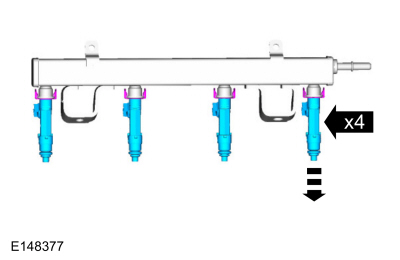
- Remove the bolts and the fuel rail.
- Remove the bolts and the fuel rail.
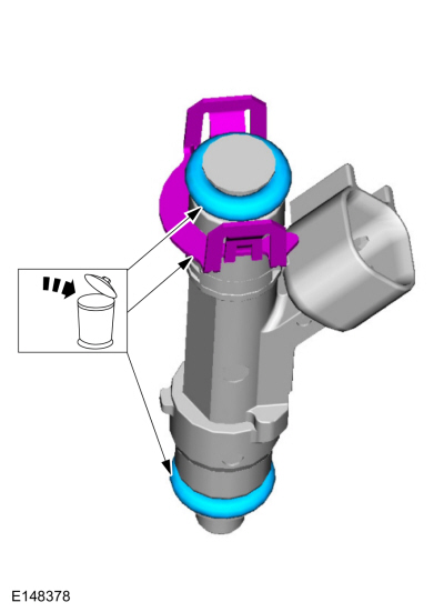
- Remove and discard the fuel injector O-rings and the fuel injector clips.
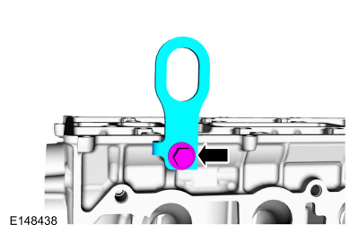
- Remove the bolt and the lifting bracket.
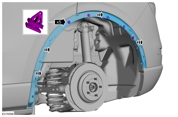
- Remove the plug.
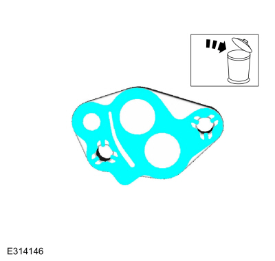
- Remove and discard the plug gasket.
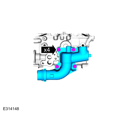
- Remove the bolts and the water outlet housing.
- Remove and discard the water outlet housing gasket.
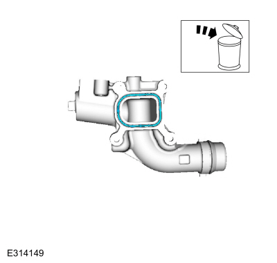
- Remove and discard the CHT sensor.

- Remove the spark plugs.
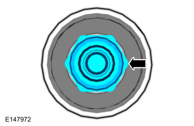
- Using the special tools, remove the valve keepers, valve spring retainers and valve springs.
Use the Special Service Tool: 303-300 (T87C-6565-A) Kit, Valve Spring Compressor, 303-350 (T89P-6565-A) Compressor, Valve Spring, 303-472 (T94P-6565-AX) Adapter, Valve Spring Compressor.
Material: Motorcraft® Multi-Purpose Spray Lubricant / XL-5-A (ESB-M1C93-B)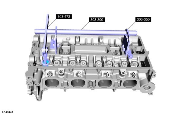
- Inspect and install new components as necessary.

- Using the special tools, remove and discard the valve stem seals.
Use the Special Service Tool: 303-468 (T94P-6510-AX) Remover, Valve Stem Seal, 307-005 (T59L-100-B) Slide Hammer.
- Remove the valves.

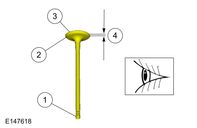
- Inspect the following valve areas:
- Valve stem end for grooves or scoring.
- Valve face and margin for pits, grooves or scratches.
- Valve head for signs of burning, erosion, warping and cracking.
- Valve margin for wear.
ASSEMBLY
- Refer to: Specifications (Engine 303-01C, Specifications).
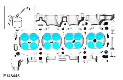
- Lubricate with clean engine oil and, using the special tool, install the valve stem seal.
Refer to: Specifications (Engine 303-01C, Specifications).
Use the Special Service Tool: 303-470 (T94P-6510-C) Installer, Valve Stem Seal.
- Using the special service tools, install the valve springs, valve spring retainers and valve keepers (collets).
Special Service Tools: 303-300 (T87C-6565-A) Kit, Valve Spring Compressor. , 303-350 (T89P-6565-A) Compressor, Valve Spring. , 303-472 (T94P-6565-AX) Adapter, Valve Spring Compressor.
Material: Motorcraft® Universal Lubricant Spray / XL-5-A (ESB-M1C93-B)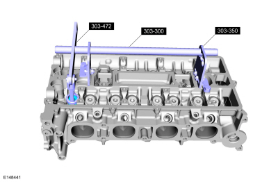
- Install the spark plugs.
Torque: 106 lb-in (12 N·m) - Install the new CHT sensor.
Torque: 106 lb-in (12 N·m)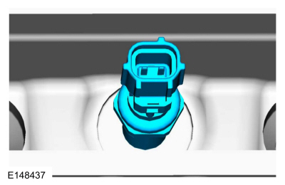
- Install a new water outlet housing gasket.

- Install the water outlet housing and hand-tighten the bolts.
- Tighten in the sequence shown.
Torque:
Stage 1: 89 lb-in (10 N·m)
Stage 2: 45°
- Tighten in the sequence shown.
- Install a new plug gasket.
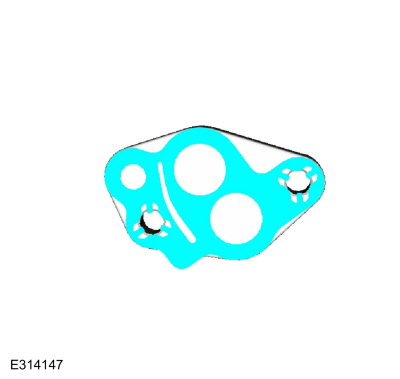
- Install the plug and bolts.
Torque: 177 lb-in (20 N·m) - Install the lifting bracket and bolt.
Torque: 39 lb-ft (53 N·m) NOTICE: Use O-rings made of special fuel-resistant material. Using standard O-rings may cause the system to leak. Do not reuse O-rings.
Install new fuel injector O-rings and fuel injector clips. Lubricate the new O-rings with clean engine oil.
Refer to: Specifications (303-01C Engine, Specifications).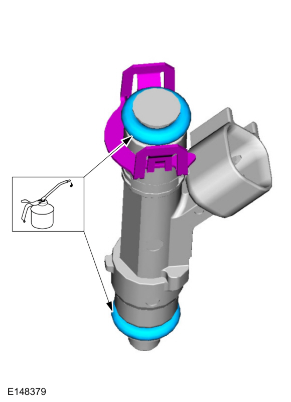
- Install the fuel injectors into the fuel rail.
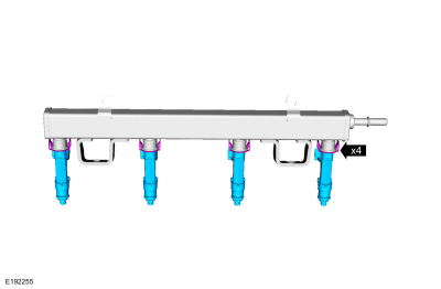
- Install the fuel rail assembly and studs.
Torque:
Stage 1: 18 lb-ft (25 N·m)
Stage 2: 30°
Test yourself
A quick Ford Escape quiz: every answer comes with an explanation and a link to the manual page.
Was this page helpful?