Powertrain
Removal and Installation - Oil Pump
In this manual: Powertrain
48steps
~318min
5/5difficulty
6special tools
Done 0 of 48
Special Service Tools / General Equipment
 |
303-290B-20 Adapter, Car-Bar TKIT-2014D-ROW3 TKIT-2014D-FL_ROW |
 |
303-F070 Engine Support Leg TKIT-1999A-F/LT TKIT-1999A-FM/FLM |
 |
303-F072 Engine Support Beam |
| Oil Drain Equipment | |
| Floor Jack | |
| Steel rule with rounded end | |
| Wood block | |
Materials
| Name | Specification |
|---|---|
| Motorcraft® High Performance Engine RTV Silicone TA-357 |
ALL-M4G323-A6 |
| Motorcraft® Metal Surface Preparation Wipes ZC-31-B |
- |
Removal
- Position the vehicle in NEUTRAL on the lift.
Refer to: Jacking and Lifting - Overview (100-02 Jacking and Lifting, Description and Operation). - Remove the hood panel grille.
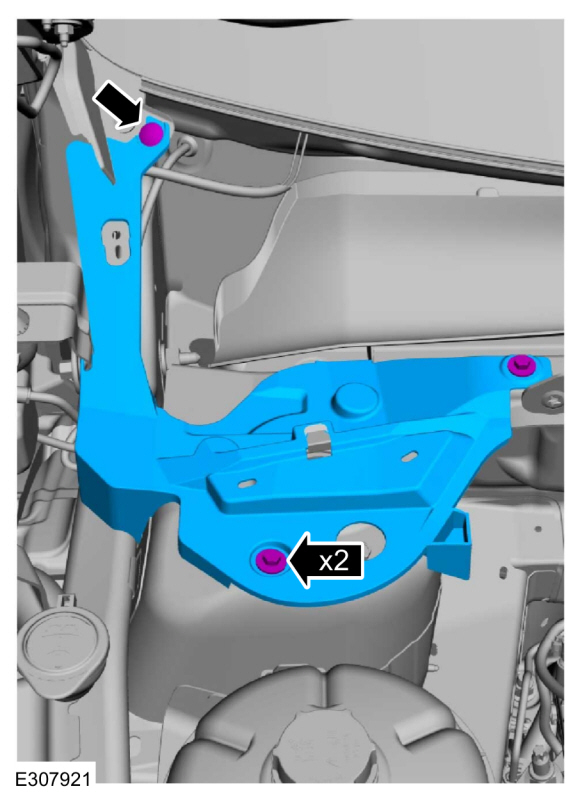
Refer to Hood Panel Grille (501-02 Front End Body Panels, Removal and Installation). - Remove the bolts, pin-type retainer and the RH hood cover.
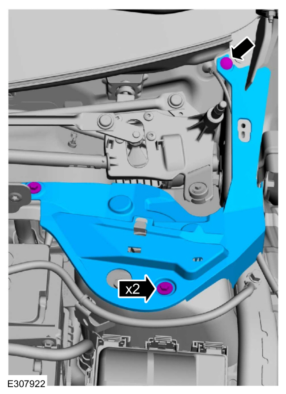
- Remove the bolts, pin-type retainer and the LH hood cover.
- Remove the coolant pump.
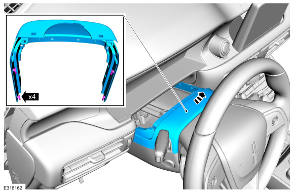
Refer to: Coolant Pump (303-03C Engine Cooling, Removal and Installation). - Disconnect the A/C compressor electrical connectors and pin-type retainers.
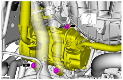
- Remove the A/C compressor nut and bolts and set them aside.
- Disconnect the wiring harness pin-type retainers, remove the clips and bracket.
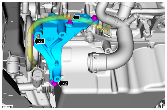
- Remove the engine front cover.
Refer to: Engine Front Cover (Engine 303-01C, Removal and Installation). - Using the 303-F070 legs and automotive adapters, assemble them to the engine support beam 303-F072 and engine support.
Install the special service tool: 303-F072 Engine Support Beam.
Install the recommended tool: 303-290B-20 Adapter, Car-Bar. The shown tool or a commercially available equivalent may be used. 303-F070 Engine Support Leg. The shown tool or a commercially available equivalent may be used.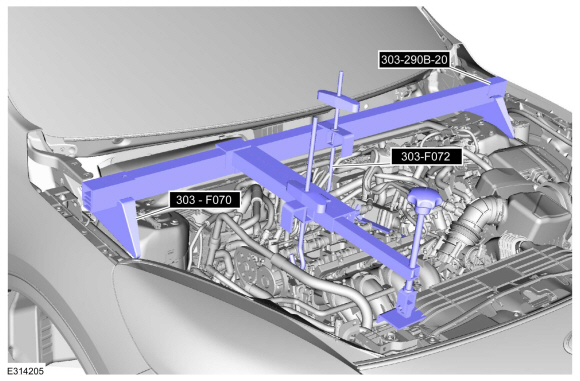
- Use the general equipment: floor jack.
Use the general equipment: wooden block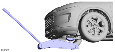
- Remove the bolt and drain the engine oil.
Use the general equipment: oil drain equipment
- Install the oil drain plug.
Torque: 21 lb-ft (28 N·m)
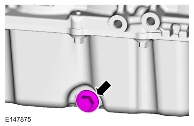
- Remove the bolt and drain the engine oil.
- Remove and discard the oil filter.
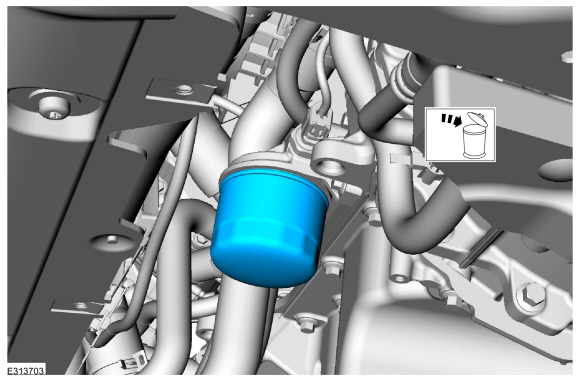
- Remove the bolt.
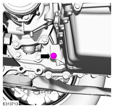
- Remove the bolts.
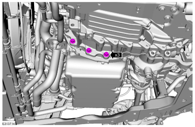
- Remove the bolts and the oil pan.
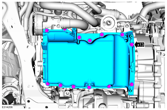
- Make sure the mating surface is clean and free of foreign material.
Refer to: RTV Sealant Surface Cleaning and Preparation (303-00 Engine System - General Information, General Procedures).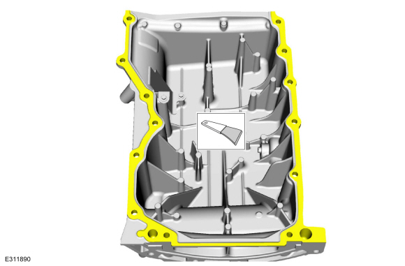
- Make sure the mating surface is clean and free of foreign material.
Refer to: RTV Sealant Surface Cleaning and Preparation (303-00 Engine System - General Information, General Procedures).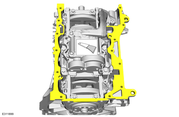
- Remove the bolts and the oil pickup tube.
- Remove and discard the oil pickup tube gasket.
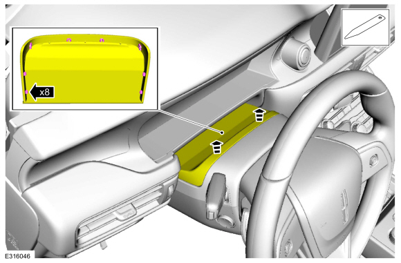
- Position the spring.
- Remove the bolts and the oil pump chain tensioner.
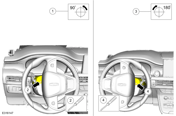
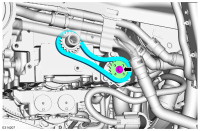
- Remove the chain from the oil pump drive sprocket.
- Remove the bolt and the oil pump drive gear.
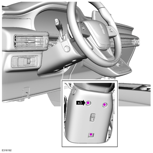
- Remove the bolts and the oil pump.
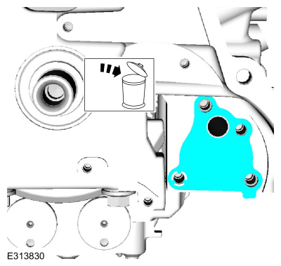
- Remove and discard the oil pump gasket.
Installation
- Prime the oil pump. Add 2 tablespoons of clean engine oil to the oil pump and rotate the oil pump by hand.
- Install a new oil pump gasket.
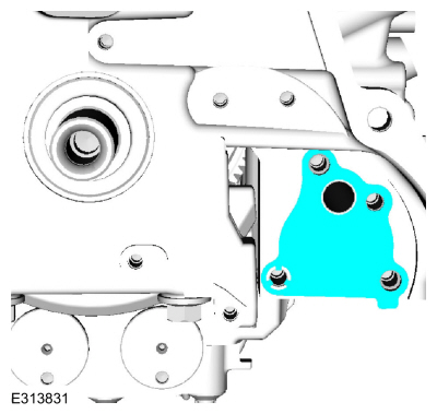
- Install the oil pump and the bolts. Tighten in the sequence shown in 2 steps.
Material: Motorcraft® Metal Surface Prep Towelettes / ZC-31-B
Torque:
Step 1: 89 lb-in (10 N·m)
Step 2: 177 lb-in (20 N·m)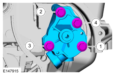
- Install the oil pump drive sprocket and the bolt.
Torque: 18 lb-ft (25 N·m)
- Install the chain onto the oil pump drive sprocket.
- Install the oil pump drive sprocket and the bolt.
- Install the oil pump chain tensioner and the bolts.
Torque: 89 lb-in (10 N·m)
- Press the tensioner spring down and position the spring under the shouldered bolt.
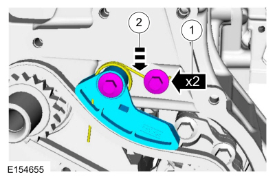
- Install the oil pump chain tensioner and the bolts.
- Lubricate a new gasket with clean engine oil and install.
- Install the oil pick-up tube and the bolts.
Torque: 89 lb-in (10 N·m)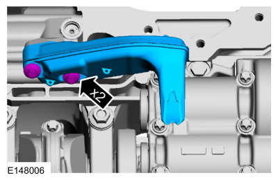
- Apply a 3 mm (0.12 in) bead of silicone sealant.
Material: Motorcraft® High Performance Engine RTV Silicone / TA-357 (WSS-M4G323-A6)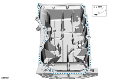
- Install the oil pan and the bolts.
- Using a straightedge, align the front face of the oil pan flush with the front face of the cylinder block.
Use common shop equipment: steel rule with rounded ends.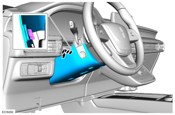
- Tighten the oil pan bolts in the sequence shown.
Torque: 177 lb-in (20 N·m)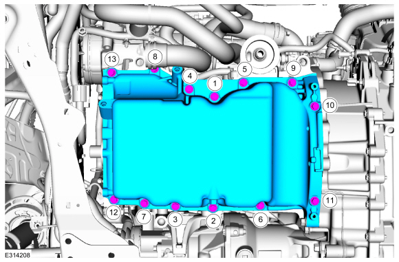
- Install the bolts.
Torque: 35 lb-ft (48 N·m) - Install the bolt.
Torque: 35 lb-ft (48 N·m) - Install a new engine oil filter.
Torque: 133 lb-in (15 N·m)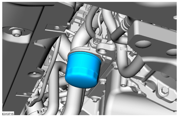
- Using a jack and a wooden block, support the engine.
Install common shop equipment: jack stand
Install common shop equipment: wooden block - Remove the engine support bracket.
Remove special service tools: 303-F072 Engine Support Plate, 303-290B-20 Adapter, Vehicle-Bar.
Remove the recommended tool: 303-F070 Engine Support Plate. - Install the front engine cover.
Refer to: Front Engine Cover (Engine 303-01C, Removal and Installation). - Install the bracket and clips and connect the wiring harness pin-type retainers.
Torque: 18 lb-ft (25 N·m) - Install the A/C compressor, install the nut and bolts.
Torque: 18 lb-ft (25 N·m)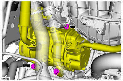
- Connect the A/C compressor electrical connectors and pin-type retainers.
- Install the coolant pump.
Refer to: Coolant Pump (303-03C Engine Cooling, Removal and Installation). - Install the left hood cover, bolts and pin retainer.
- Install the right hood cover, bolts and pin retainer.
- Install the hood panel grille.
Refer to Hood Panel Grille (501-02 Front End Body Panels, Removal and Installation). - Fill the engine with clean engine oil.
Refer to: Specifications (303-03C Engine Cooling, Specifications).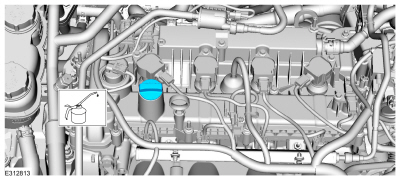
Test yourself
A quick Ford Escape quiz: every answer comes with an explanation and a link to the manual page.
Was this page helpful?