Powertrain
Removal and Installation — Valve Cover
In this manual: Powertrain
30steps
~190min
5/5difficulty
2special tools
Done 0 of 30
Special Service Tools / General Equipment
 |
205-153 (T80T-4000-W) Handle |
 |
303-1247 VCT Spark Plug Tube Seal Remover and Installer TKIT-2006UF-FLM TKIT-2006UF-ROW |
Materials
| Name | Specification |
|---|---|
| Motorcraft® High Performance Engine RTV Silicone TA-357 |
ALL-M4G323-A6 |
| Motorcraft® Metal Surface Preparation Wipes ZC-31-B |
- |
Removal
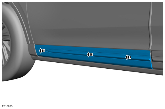
- Position the vehicle in NEUTRAL on the lift.
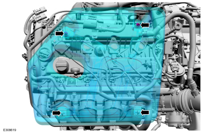
Refer to: Jacking and Lifting - Overview (100-02 Jacking and Lifting, Description and Operation). - Remove the nut, release the engine outer cover from the ball studs, then remove the cover.
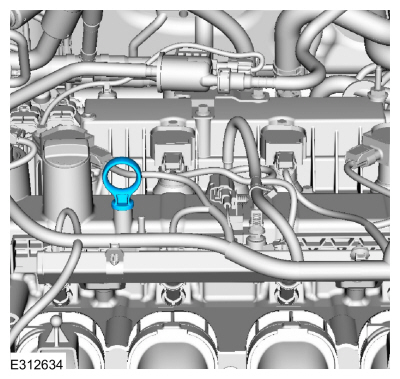
- Remove the oil level indicator.
- Remove the ignition coil from the spark plug.
Refer to: Coil-on-Plug Ignition Coil (303-07C Engine Ignition, Removal and Installation). - Disconnect the vent hoses.
Refer to: Quick Release Coupling (310-00G).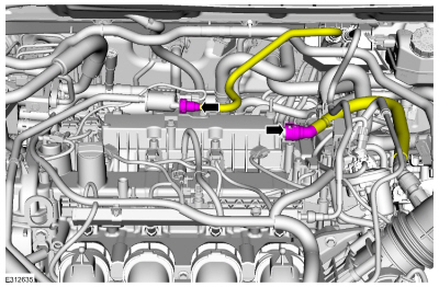
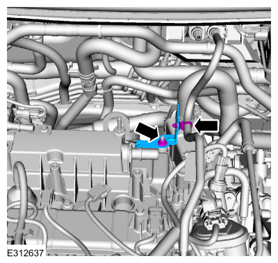
- Disconnect the pin retainer, remove the nut and the fuel rail bracket.
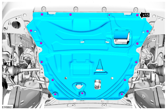
- Remove the brackets and the lower splash shield.
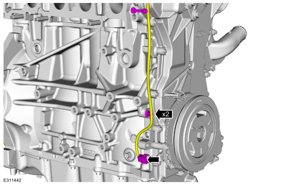
- Disconnect the CKP electrical connector and remove the pin retainers.
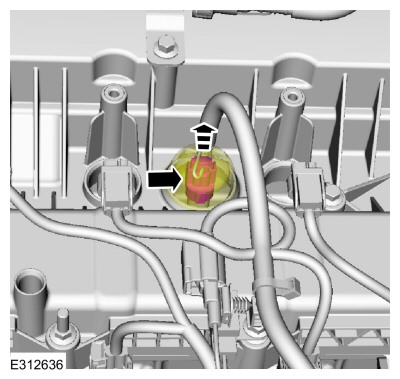
- Position the boot and disconnect the CHT sensor electrical connector.
- Disconnect the wiring harness retainer.
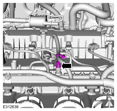
- Remove the nut and set the radio capacitor aside.
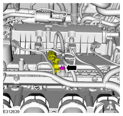
- Disconnect the electrical connectors, remove the wiring harness retainers and set aside.
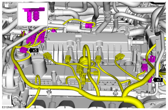
- Loosen the fasteners and remove the valve cover.
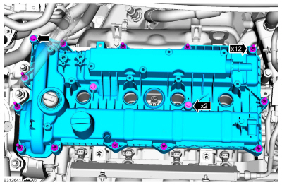
- If necessary, remove the VCT seals using special tools.
Use special service tools: 303-1247 VCT Spark Plug Tube Seal Remover and Installer, 205-153 (T80T-4000-W) Handle.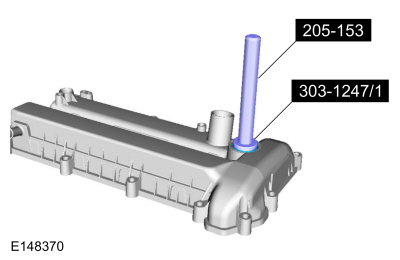
- Clean the sealing surfaces.
Material: Motorcraft® Metal Surface Preparation Wipes. / ZC-31-B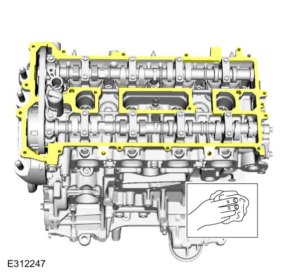
Installation
- If removed, install the VCT seals using the special tools.
Use the Special Service Tools: 303-1247 VCT Spark Plug Tube Seal Remover and Installer, 205-153 (T80T-4000-W) Handle.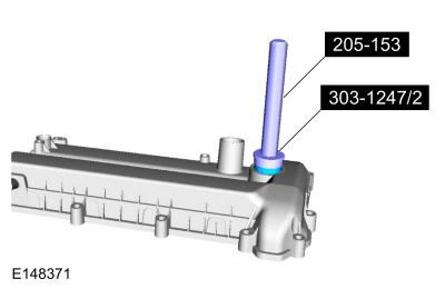
- Inspect and, if necessary, install new valve cover gaskets.
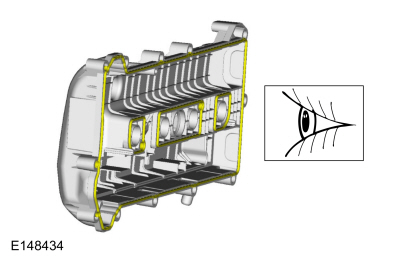
- Apply a 6 mm (0.24 in) bead of silicone sealant.
Material: Motorcraft® High Performance Engine RTV Silicone / TA-357 (WSE-M4G323-A6)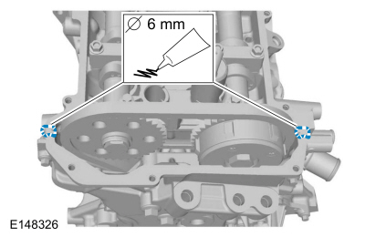
- Install the valve cover and tighten the bolts in the sequence shown.
Torque: 89 lb-in (10 N·m)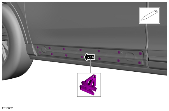
- Position the wiring harness, connect the electrical connectors and secure the retainers.
- Position the radio capacitor and install the nut.
Torque: 89 lb-in (10 N·m) - Secure the wiring harness retainer.
- Connect the CHT sensor electrical connector and slide the boot into place.
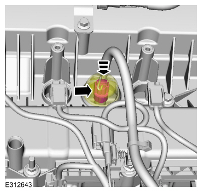
- Connect the CKP electrical connector and secure the pin-type retainers.
- Install the lower shield and brackets.
- Install the fuel line bracket and nut, and secure the pin-type retainer.
- Connect the vent tubes.
Refer to: Quick Release Coupling (310-00G). - Install the ignition coils onto the spark plugs.
Refer to: Ignition Coil-On-Plug (303-07C Engine Ignition, Removal and Installation). - Install the oil level indicator.
- Install the engine outer cover onto the ball studs, then install and tighten the nut.
Torque: 97 lb-in (11 N·m)
Test yourself
A quick Ford Escape quiz: every answer comes with an explanation and a link to the manual page.
Was this page helpful?