Powertrain
Installation - Engine
In this manual: Powertrain
84steps
~509min
5/5difficulty
1special tools
Done 0 of 84
Special Service Tools / General Equipment
 |
303-476 (T94P-9472-A) Socket, Exhaust Gas Oxygen Sensor TKIT-1994-LM/M TKIT-1994-F TKIT-1994-FLM/FM |
| Floor crane | |
| Adjustable mounting arm | |
| Hose Clamp Removal/Installation Tool | |
| Fluid Container | |
| Powertrain jack | |
| Wood block | |
Materials
| Name | Specification |
|---|---|
| Motorcraft® High-Temperature Nickel Anti-Seize Lubricant XL-2 |
- |
- Inspect the cylinder block dowels. If the dowels are damaged or missing, install new cylinder block dowels.

- Install the engine to the transmission.
Use the common service equipment: floor crane
- If the dowel pins were pulled out of the cylinder block during removal, install new dowel pins into the cylinder block.
- Install the right engine mount to the transmission bolts.
Torque: 35 lb-ft (48 N·m)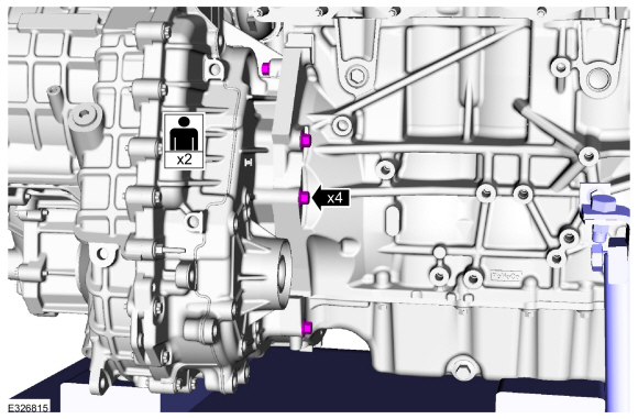
- Install the left engine mount to the transmission bolts.
Torque: 35 lb-ft (48 N·m)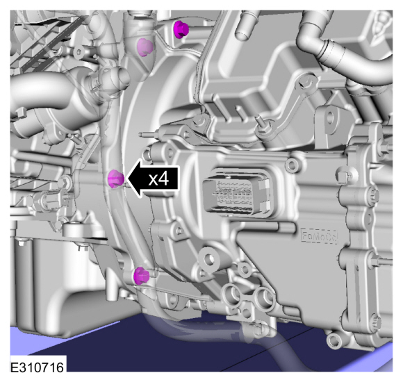
- Install the right adjustable mount link.
Use the common service equipment: adjustable mount link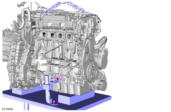
- Install the left adjustable mount link.
Use the common service equipment: adjustable mount link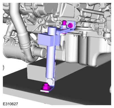
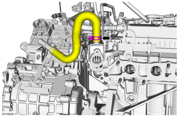
- Install the EGR cooler hose.
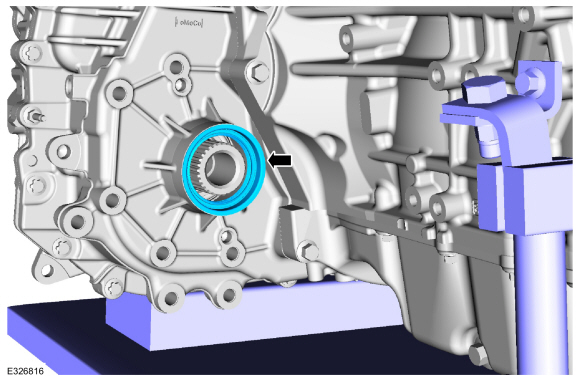
- Install a new PTU onto the transmission compression seal.
- At this stage, install the PTU and bolts and tighten by hand.

- Tighten in the sequence shown.
Torque: 81 lb-ft (110 N·m)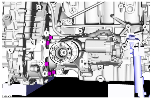
- Install the vent hose retainer.

- Install a new exhaust manifold gasket.

- Install new nuts and the exhaust manifold.
Torque: 41 lb-ft (55 N·m)
- Install the exhaust manifold heat shield and bolts.
Torque: 89 lb-in (10 N·m)
- Clean and inspect the gasket surface and studs. Replace the studs if necessary.
Torque: 159 lb-in (18 N·m)
- Install new exhaust gas recirculation (EGR) cooler inlet pipe gaskets.
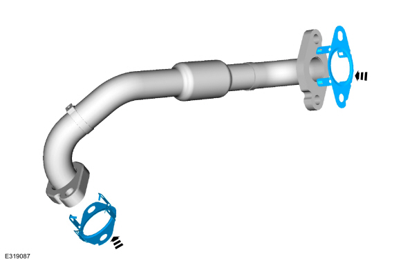
- Install the EGR cooler inlet pipe and tighten the fasteners by hand.

- Tighten in the sequence shown.
Torque:
1: 89 lb-in (10 N·m)
2: 18 lb-ft (24 N·m)
1: 18 lb-ft (24 N·m)
3: 89 lb-in (10 N·m)
4: 18 lb-ft (24 N·m)
3: 18 lb-ft (24 N·m)
- Calculate the correct torque wrench setting for the following torque. Refer to the Torque Wrench Adapter Formula in Apex. Install the HO2S sensor.
Use special service tool: 303-476 (T94P-9472-A) Exhaust Gas Oxygen Sensor Socket.
Material: Motorcraft® High Temperature Nickel Anti-Seize Lubricant / XL-2
Torque: 35 lb-ft (48 N·m)
- Install the wire harness bolts and brackets.
- Connect the HO2S sensor electrical connector.
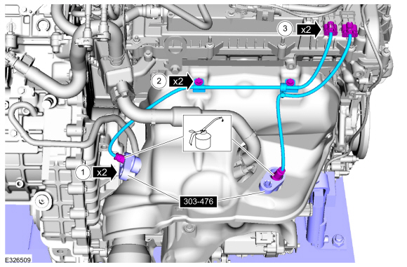
- Calculate the correct torque wrench setting for the following torque. Refer to the Torque Wrench Adapter Formula in Apex. Install the HO2S sensor.
- Remove the floor crane and the commercially available quick-release link and chain.
Use the common service equipment: floor crane
- Install the engine and transmission to the vehicle.
Use the common service equipment: power jack
Use the common service equipment: adjustable mount link
Use the common service equipment: wood block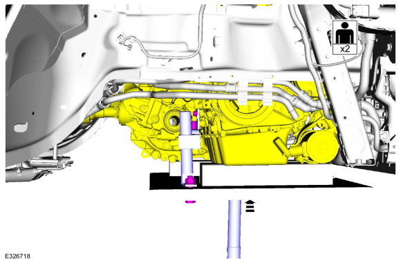
- Hand-tighten the transmission mount insulator bolts.
- Hand-tighten the engine mount fasteners.
- Tighten the engine mount nuts.
Torque: 81 lb-ft (110 N·m)
- Tighten the engine mount bolts.
Torque: 129 lb-ft (175 N·m)

- Tighten the engine mount nuts.
- Tighten the transmission mount insulator bolts.
Torque: 92 lb-ft (125 N·m) - Remove the adjustable mount link.
Use the common service equipment: power jack
Use the common service equipment: adjustable mount link
Use the common service equipment: wood block - Remove the adjustable mount link and the powertrain jack.
Use the common service equipment: power jack
Use the common service equipment: adjustable mount link
Use the common service equipment: wood block
- Install the front subframe.
Refer to: Front Subframe (502-00 Uni-Body, Subframe and Mounting System, Removal and Installation).
Install the roll restrictor bracket.- Install the stud and bolts.
Torque: 81 lb-ft (110 N·m)
- Install the fork bolt.
Torque: 129 lb-ft (175 N·m)

- Install the stud and bolts.
- Install the PTU support bracket and bolts.
Torque: 35 lb-ft (48 N·m)
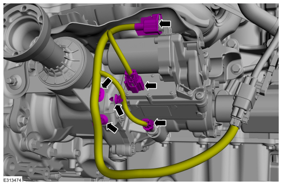
- Connect the PTU temperature sensor, engine connectors and retainers.
- Install the driveshaft into position and make sure the alignment marks are aligned.
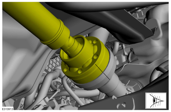
- Install new PTU flange bolts.
Torque: 26 lb-ft (35 N·m)
- Install the intermediate shaft.
Refer to: Intermediate Shaft (205-04 Front Drive Axle Shafts, Removal and Installation). - Install the left front axle shaft.
Refer to: Front Axle Shaft, Left (205-04 Front Axle Shafts, Removal and Installation). - Install the coolant hoses.
Use common service equipment: hose clamp removal and installation tool.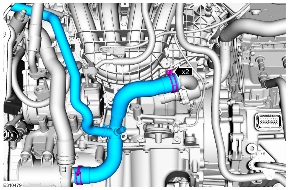
- Install the engine oil filter.
Torque: 133 lb-in (15 N·m)
- Install new O-rings and gaskets, the A/C line and nuts.
Torque: 159 lb-in (18 N·m)
- Install the transmission coolant line and bolt.
Use the common service equipment: fluid container
Torque: 18 lb-ft (25 N·m)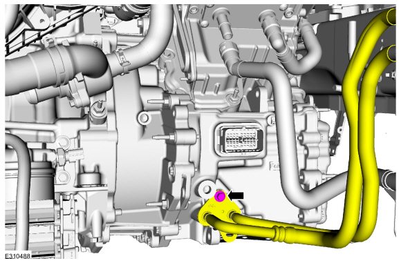
- Connect the upper radiator hose.
Use the common service equipment: hose clamp removal/installation tool.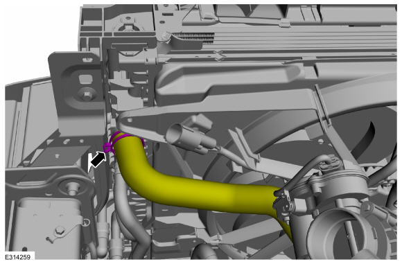
- Connect the coolant hose.
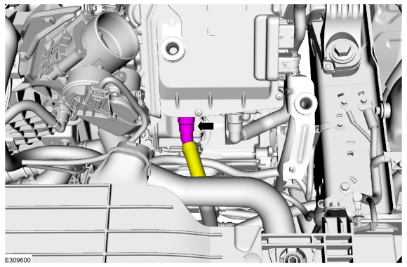
- Connect the electrical connectors and install the wiring harness retainers.
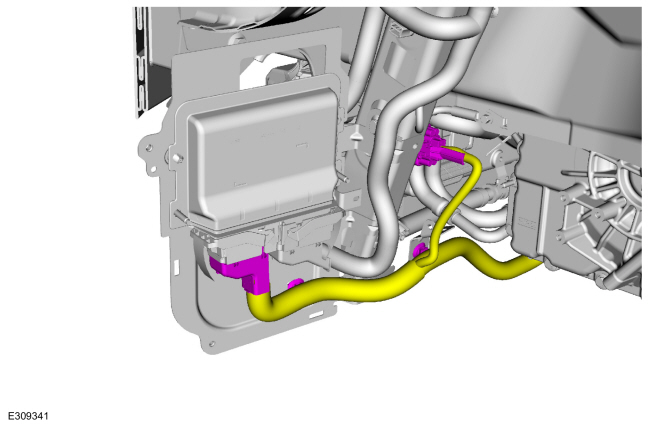
- Install the PCM cover and bolts.

- Connect the transmission electrical connector and install the wiring harness retainers.
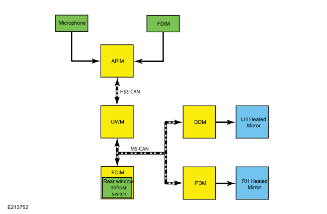
- Install the wiring harness bracket and bolts.
- Connect the high-voltage cable to the ISC and tighten the retainer.
Torque: 97 lb-in (11 N·m)

- Connect C199A (40-way connector) and lock the lever.
- Connect C199B (22-way connector).
- Install the wiring harness retainer.
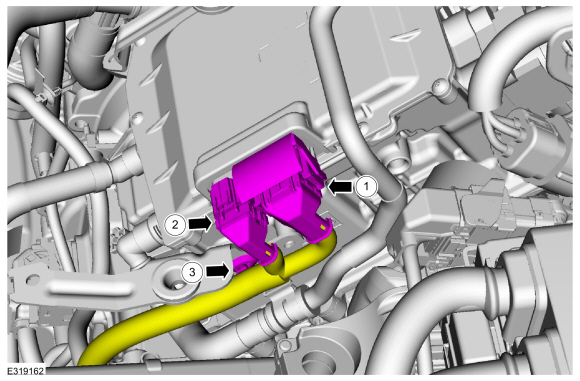
- Connect the A/C electrical connectors and install the wiring harness retainers.
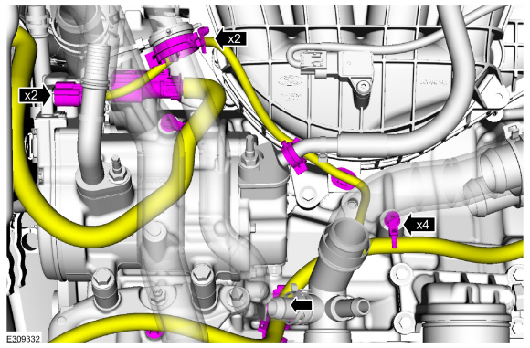
- Connect the coolant pump electrical connector and install the wiring harness retainers.
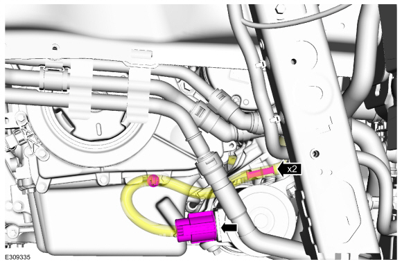
- Install the coolant hoses and clamps.
Use the common service equipment: hose clamp removal/installation tool.
- If equipped.
Connect the oil cooler hose.
Use the common service equipment: hose clamp removal/installation tool.
- Connect the coolant hose.
Use common service equipment: hose clamp removal and installation tool.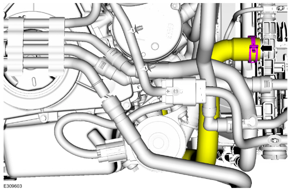
- Connect the coolant hose.
Use common service equipment: hose clamp removal and installation tool.
- If equipped with a block heater.
Connect the cylinder block heater electrical connector.
- If equipped with a block heater.
Install the block heater electrical connector cover.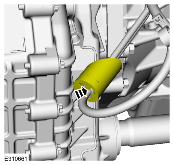
- Install the oil pan bolts.
Torque: 35 lb-ft (48 N·m)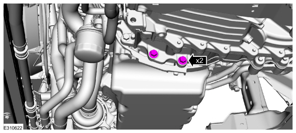
- Install the left subframe support bracket and new bolts.
Torque: 22 lb-ft (30 N·m)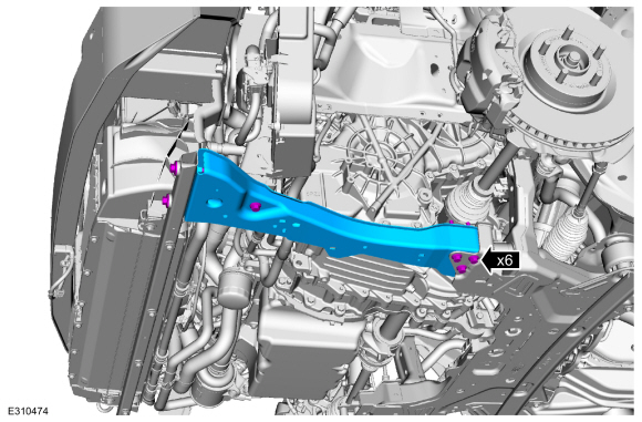
- Install the right subframe support bracket and new bolts.
Torque: 22 lb-ft (30 N·m)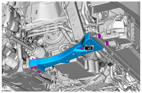
- Install the exhaust manifold bracket and bolts.
Torque: 18 lb-ft (25 N·m)
- Install a new exhaust clamp.
Torque: 17 lb-ft (23 N·m)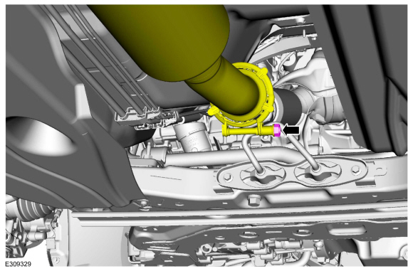
- Install the bracket and nuts.
Torque: 35 lb-ft (48 N·m)
NOTICE: Do not bend or twist the exhaust pipe. Failure to follow these instructions may damage the flexible pipe.
Remove the flex exhaust pipe support.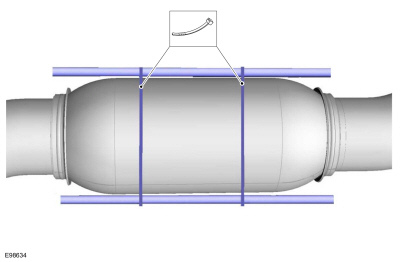
- Install the coolant hoses and pin retainers.
Use the common service equipment: hose clamp removal/installation tool.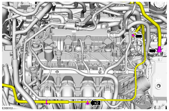
- If equipped.
Reposition the block heater wiring harness and attach the clips.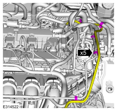
- Remove the commercially available lifting eye.
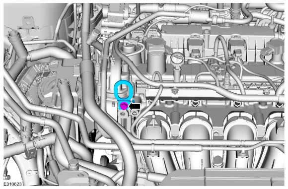
- Install the ground wire.
Torque: 133 lb-in (15 N·m)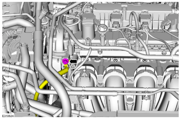
- Connect the coolant hoses.
Use the common service equipment: hose clamp removal/installation tool.
- Connect the fuel vapor and fuel supply tubes.
Refer to: Quick Release Coupling (310-00C Fuel System - General Information, General Procedures).
Refer to: Spring Lock Couplings (310-00C Fuel System - General Information, General Procedures).
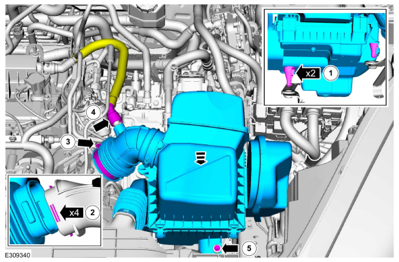
- Install the air cleaner.
- Connect the air cleaner inlet tube.
- Tighten the clamp.
- Connect the breather tube.
- Install the bolt.
- Position the steering column shaft and install a new bolt.
Torque: 46 lb-ft (63 N·m)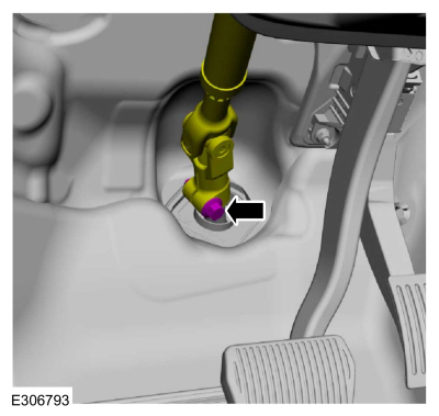
- Using a holding device, hold the steering wheel in the straight-ahead position.
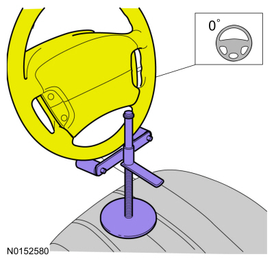
- Install the following components:
- Install the degas bottle.
Refer to: Degas Bottle (303-03C Engine Cooling, Removal and Installation). - Install the front bumper cover.
Refer to: Front Bumper Cover (501-19 Bumpers, Removal and Installation). - Install the front fender splash shields.
Refer to: Fender Splash Shield (501-02 Front End Body Panels, Removal and Installation).
- Install the degas bottle.
- Fill the engine with clean engine oil.
Refer to: Specifications (303-03C Engine Cooling, Specifications).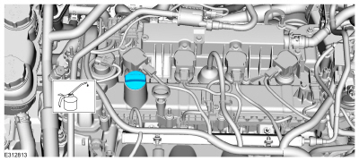
- Connect the battery cables.
Refer to: Battery Cables - Duratec 2.5 L - Hybrid (121 kW/164 L hp) (BG) (414-01 Battery, Mounting and Cables, Removal and Installation). - Service the vehicle high-voltage system.
Refer to: High-Voltage System Disabling (414-03A High-Voltage Battery, Mounting and Cables, General Procedures). - Relieve the fuel system pressure.
Refer to: Fuel System Pressure Release (310-00C Fuel System - General Information, General Procedures). - Fill and bleed the cooling system.
Refer to: Engine Cooling System Draining, Vacuum Filling and Air Bleeding (303-03C Engine Cooling - General Procedures). - Fill and bleed the electric drive cooling system.
Refer to: Cooling System Filling and Air Bleeding (303-03D Electric Transmission Cooling - Hybrid Electric Vehicle (HEV), General Procedures). - Charge the air conditioning system.
Refer to: Air Conditioning (A/C) System Recovery, Evacuation and Charging - 2.5 L Duratec - Hybrid (121 kW/164 L hp) (BG) (412-00 Climate Control System - General Information, General Procedures).
Refer to: Air Conditioning (A/C) System Recovery, Evacuation and Charging - Hybrid Electric Vehicle (HEV), vehicles with: R134a Refrigerant (412-00 Climate Control System - General Information - 2.5 L Duratec - Hybrid (121 kW/164 L hp) (BG)). - Check and, if necessary, add transmission fluid.
Refer to: Transmission Fluid Level Check (307-01B Automatic Transmission - Automatic Transmission - HF45, General Procedures). - Check the PTU (power transfer unit) fluid level.
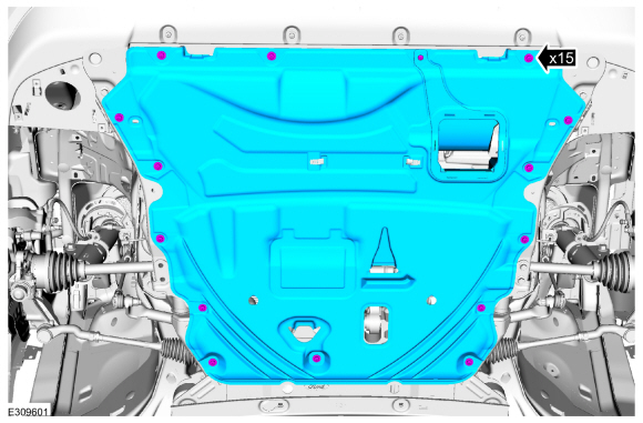
Refer to: Front Axle Shaft, Left (205-04 Front Axle Shafts, Removal and Installation). - Install the lower shield and brackets.
- If the engine appearance cover stud is loosened or removed, install/tighten it in the valve cover.
Torque: 62 lb-in (7 N·m)
- Position the engine appearance cover on the engine so that the bushings are aligned with the studs.
- Press down on the engine appearance cover at each bushing location to attach the bushings to the studs.
- Install the engine appearance cover nut.
Torque: 44 lb-in (5 N·m)

- If the engine appearance cover stud is loosened or removed, install/tighten it in the valve cover.
- Start the vehicle and check the exhaust system for leaks.
- If the engine was disassembled, perform the misfire monitor neutral profile correction procedure.
Test yourself
A quick Ford Escape quiz: every answer comes with an explanation and a link to the manual page.
Was this page helpful?