Engine - Disassembly
Special Service Tools / General Equipment
 |
100-001 (T50T-100-A) Slide hammer |
 |
300-OTC1819E Floor Crane 2200 lb, Folding |
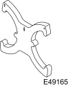 |
303-1097 Locking Tool, Variable Camshaft Timing Oil Control Valve TKIT-2010B-FLM TKIT-2010B-RYAD |
 |
303-1502 Engine Lifting Device TKIT-2012A-FL TKIT-2012A-RYAD |
 |
303-409 (T92C-6700-CH) Remover, Crankshaft Seal TKIT-1992-FX/FMX/FLMX TKIT-1993-LMX/MX |
 |
303-748 Crankshaft Locking Tool TKIT-2010B-FLM TKIT-2010B-RHD |
 |
307-005 (T59L-100-B) Slide Hammer |
 |
308-375 Remover, Input Shaft Seal TKIT-2005U-M TKIT-1999-F/FLM/LT |
 |
310-206 Puller, Fuel Injector TKIT-2009A-FLM |
| Heat gun | |
| Hose Clamp Removal/Installation Tool | |
Materials
| Name | Specification |
|---|---|
| Motorcraft® Metal Brake Parts Cleaner PM-4-A, PM-4-B, APM-4-C |
- |
NOTICE: Do not loosen or remove the crankshaft pulley bolt without first installing the special service tools. The crankshaft pulley and the crankshaft timing sprocket are not connected to the crankshaft. Before any repair that requires loosening or removing the crankshaft pulley bolt, the crankshaft and camshafts must be locked with the special service tools, otherwise serious engine damage may occur.
NOTICE: Cleanliness is extremely important when repairing the engine. Any foreign material, including material created during the cleaning of gasket surfaces, that enters the oil passages, coolant passages or oil pan may cause engine failure.
NOTICE: Do not breathe dust and do not use compressed air to blow dust from storage containers or friction components. Remove dust using a method approved by the government. Friction component dust may cause cancer and lung disease. Exposure to potentially hazardous components may occur when dust is generated during repair of friction parts such as brake pads and clutch discs. Exposure may also cause skin, eye and respiratory irritation, may cause allergic reactions and/or may lead to other chronic health effects. If irritation does not go away, seek medical attention or advice. Failure to follow these instructions may result in serious injury.
Evenly loosen the 6 clutch pressure plate-to-flywheel bolts, 2 turns at a time.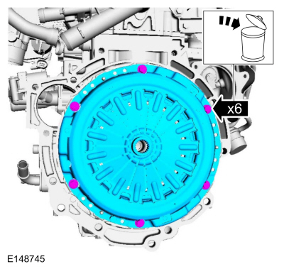
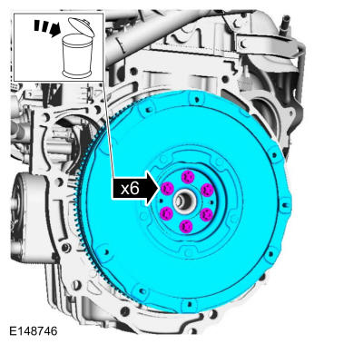
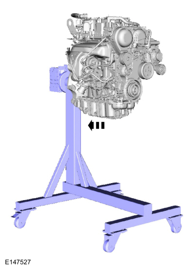
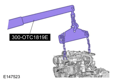
- Remove the special service tool: 300-OTC1819E 2200 lb Floor Crane, Folding.
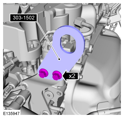
- Remove the special service tool: 303-1502 Engine Lifting Device.
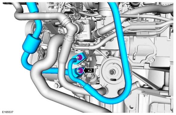
- If equipped with a block heater.

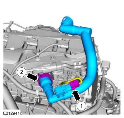
- If equipped.
- Use common service equipment: hose clamp removal/installation tool.
- Use common service equipment: hose clamp removal/installation tool.
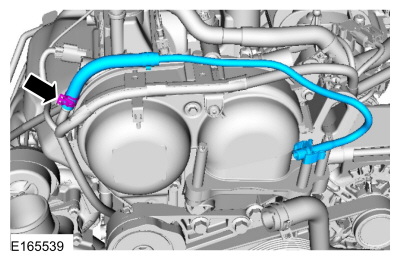
- Use common service equipment: hose clamp removal/installation tool.

- Use common service equipment: hose clamp removal/installation tool.
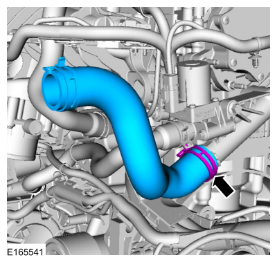
- Use common service equipment: hose clamp removal/installation tool.
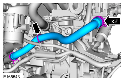
- Use common service equipment: hose clamp removal/installation tool.
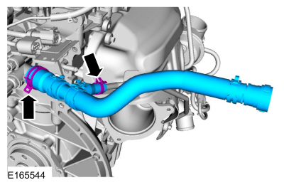
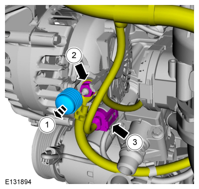
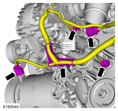

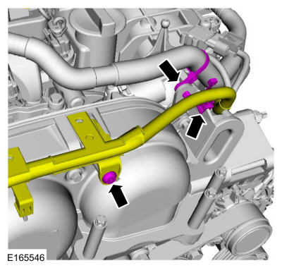
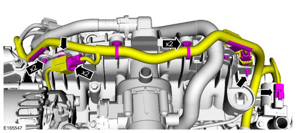
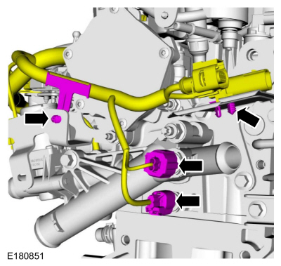
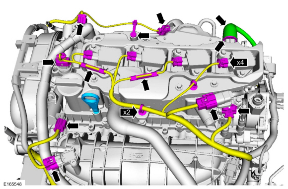
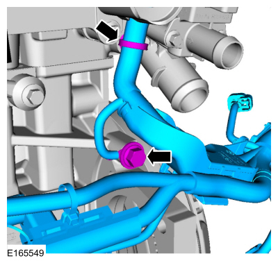
- Use common service equipment: hose clamp removal/installation tool.
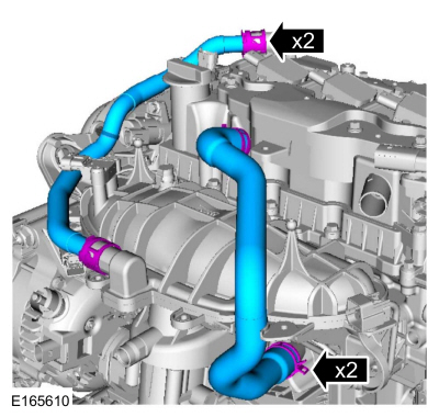
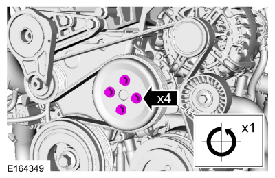
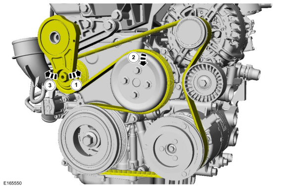
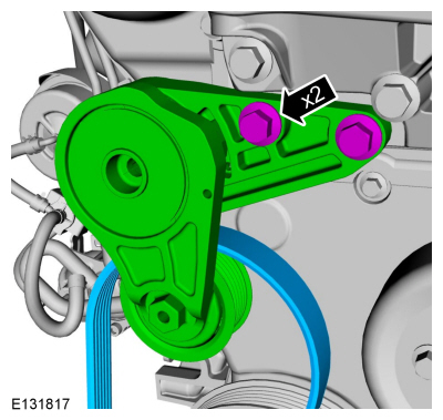
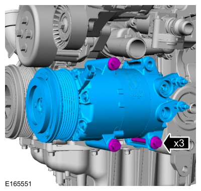
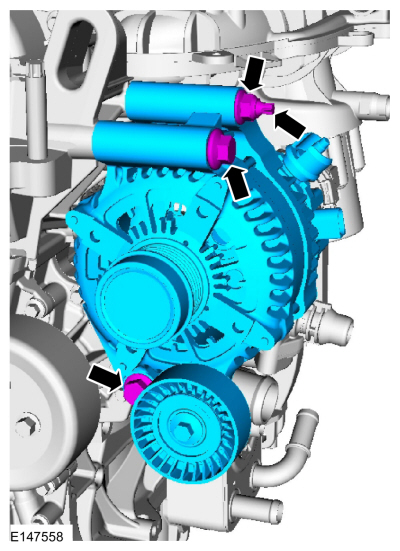
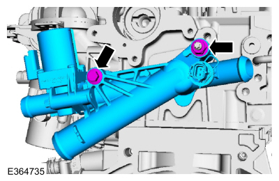
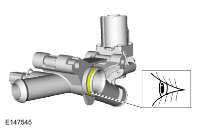

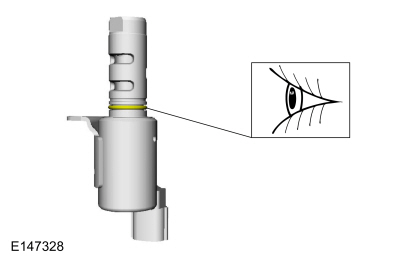
NOTICE: When removing or installing the high-pressure fuel pump, insulate the openings to reduce the risk of damage.
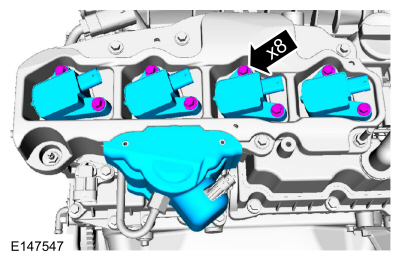

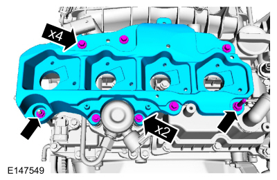
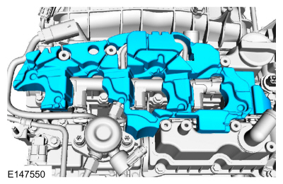
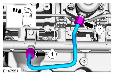
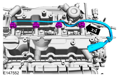
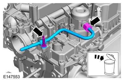
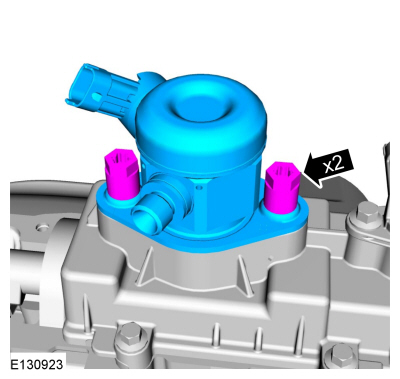
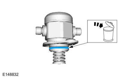
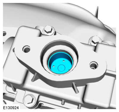
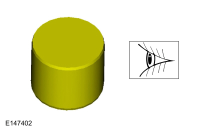
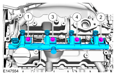
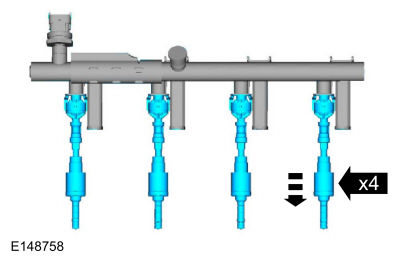
NOTICE: Pull the fuel rails in the direction of the fuel injector axis, otherwise the injectors may be damaged.
- Remove all fuel injectors remaining in the fuel rail.
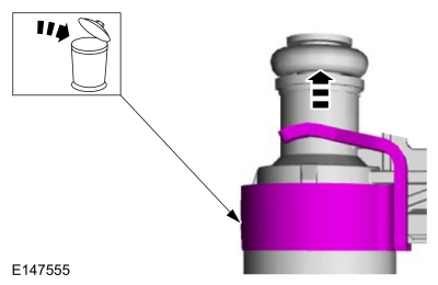
- Use the special service tool: 307-005 (T59L-100-B) Slide Hammer.
- Use the special service tool: 310-206 Fuel Injector Puller.

NOTICE: Do not place the valve cover sealing surface on a bench, as the check valve and divider leg may break.
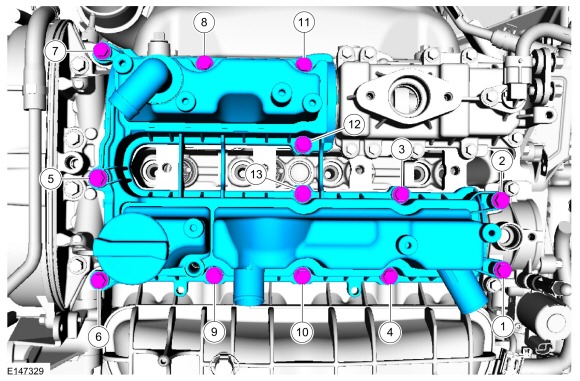
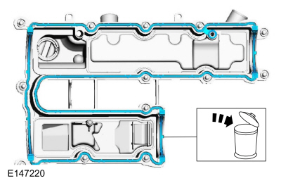
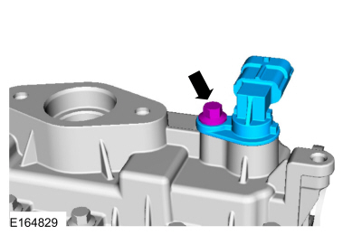
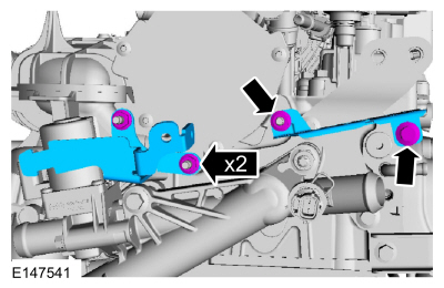
NOTICE: Use a heat gun to soften the flange sealant to assist in removing the fuel pump mounting bracket. Failure to follow these instructions may damage the fuel pump mounting bracket.
Use the general equipment: heat gun.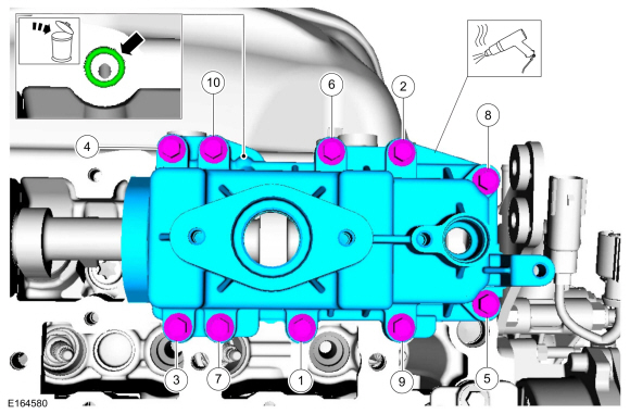
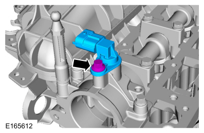
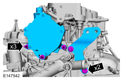
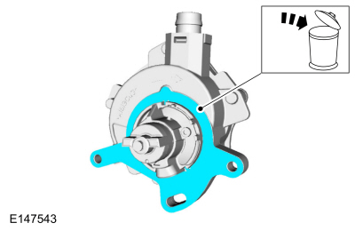
NOTICE: Use a heat gun to soften the flange sealant to assist in removing the brake vacuum pump mounting bracket. Failure to follow these instructions may damage the brake vacuum pump mounting bracket.
Use the general equipment: heat gun.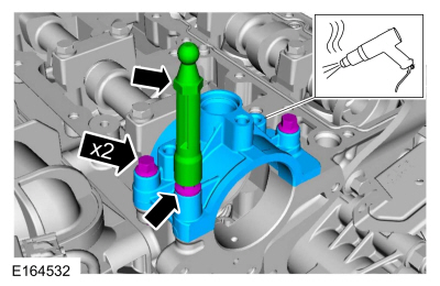
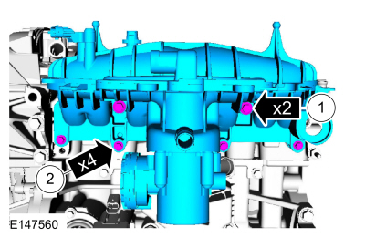

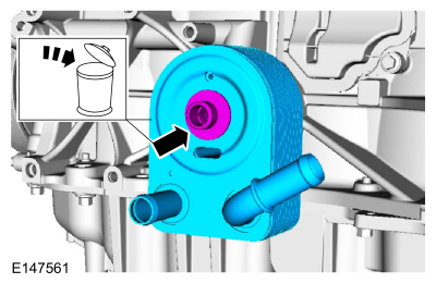
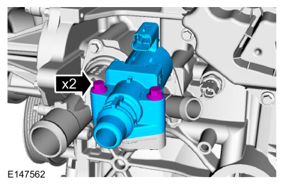
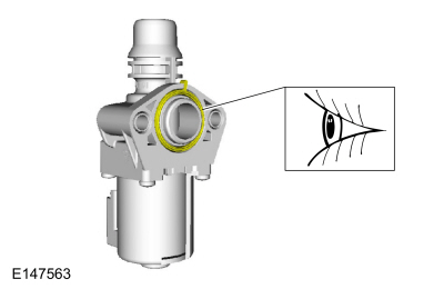
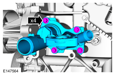
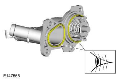
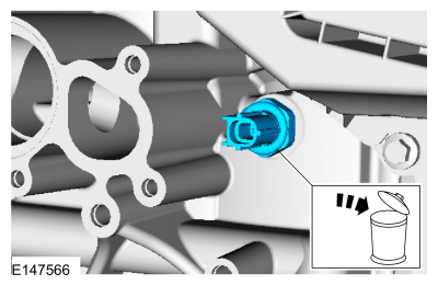
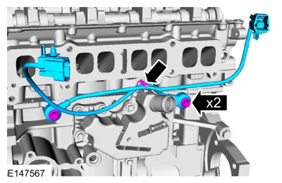
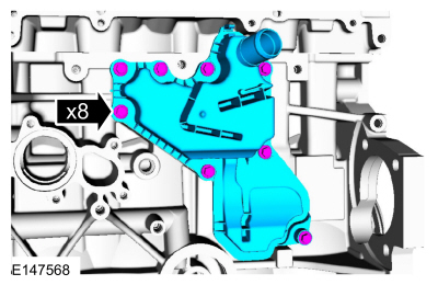
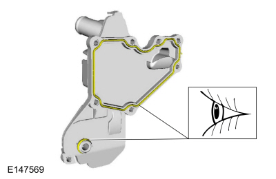
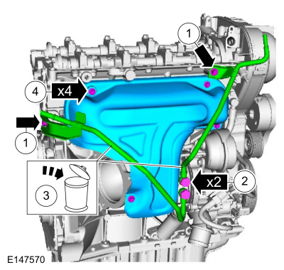
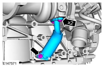
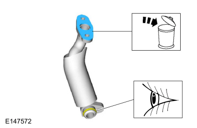
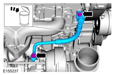
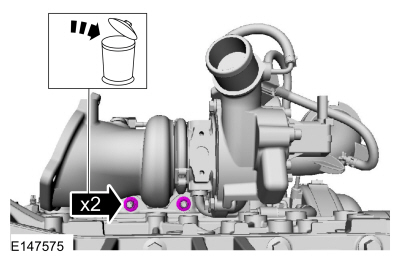
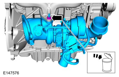
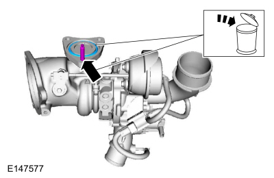
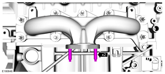
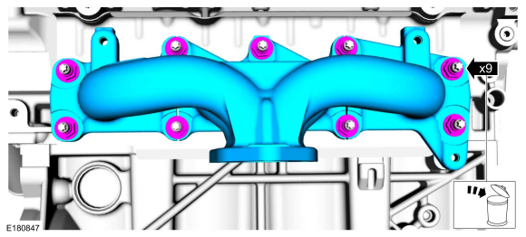
- Refer to: Exhaust Manifold Cleaning and Inspection (303-00 Engine System - General Information, General Procedures).
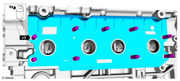
- If equipped with a block heater.
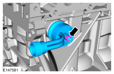
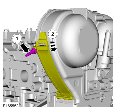
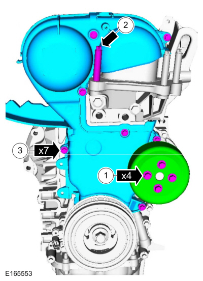
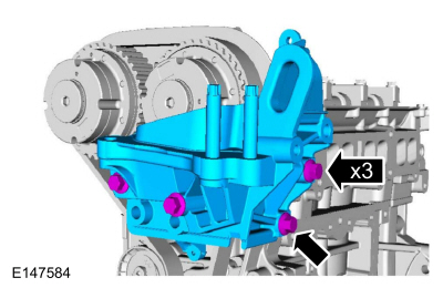
- 11 o'clock position.

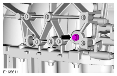
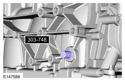
- Install the special service tool: 303-748 Crankshaft Locking Tool.
- Slowly rotate the crankshaft clockwise until the crankshaft counterweight is against the TDC timing pin. The engine is now at TDC.
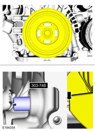
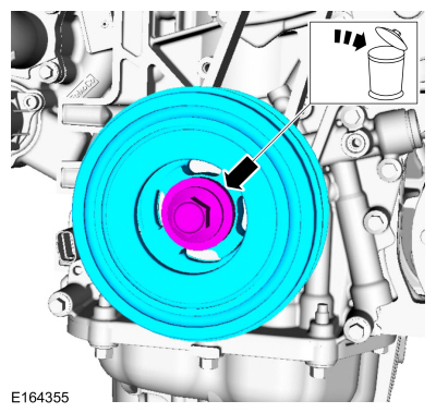
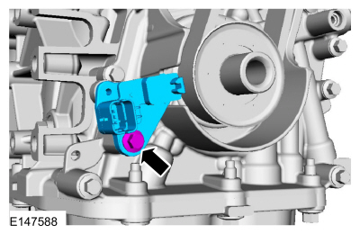
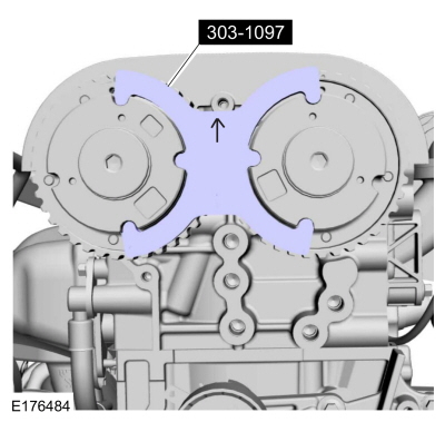
- Install the special service tool: 303-1097 Locking Tool, Variable Camshaft Timing Oil Control Valve.
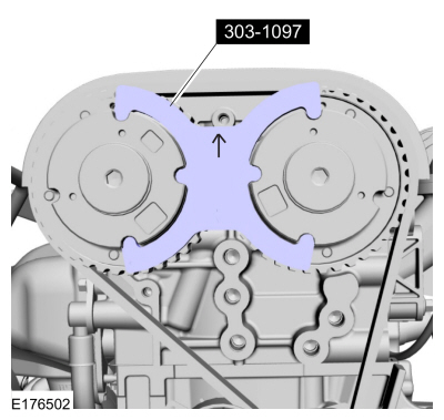
- Install the retaining pin.
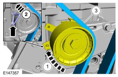
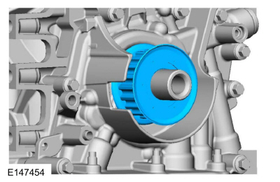
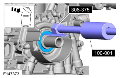
- Use the special service tools: 308-375 Input Shaft Seal Remover, 100-001 (T50T-100-A) Slide Hammer.
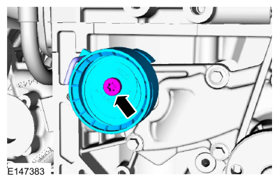
- Torque: 89 lb-in (10 N·m)
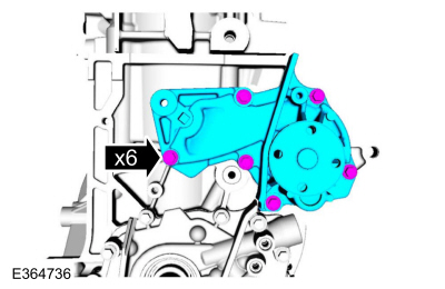
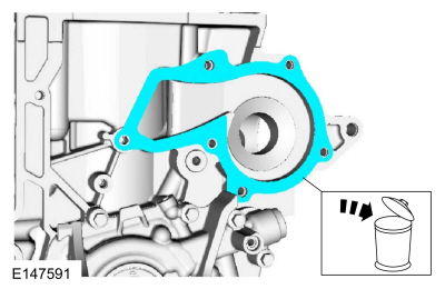
- Remove the special service tool: 303-1097 Locking Tool, Variable Camshaft Timing Oil Control Valve.
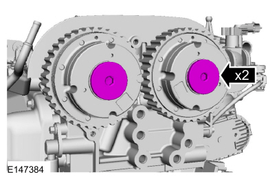
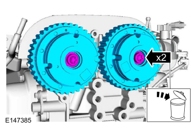
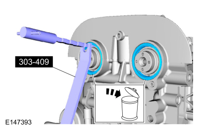
- Use the special service tool: 303-409 (T92C-6700-CH) Crankshaft Seal Remover.
NOTICE: Use a heat gun to soften the flange sealant to assist in removing the camshaft cap. Failure to follow these instructions may result in damage to the camshaft cap.
NOTICE: Do not pry on the camshafts during removal as this may damage the camshafts.
Use the general equipment: heat gun.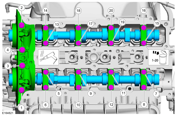

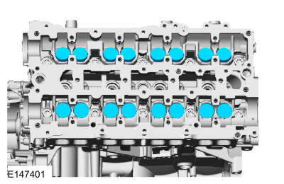
- Install new components if necessary.
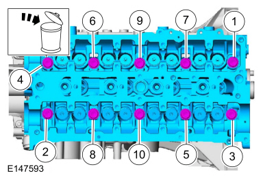
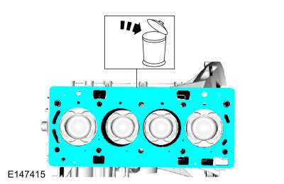
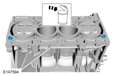
- Refer to: Cylinder Head Distortion (303-00 Engine System - General Information, General Procedures).
Refer to: Cylinder Block Distortion (303-00 Engine System - General Information, General Procedures). - Remove the special service tool: 303-748 Crankshaft Locking Tool.
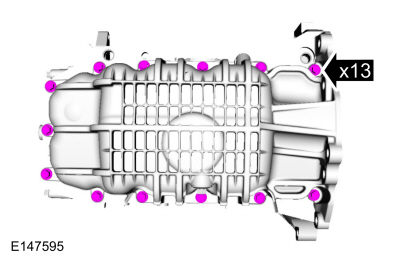
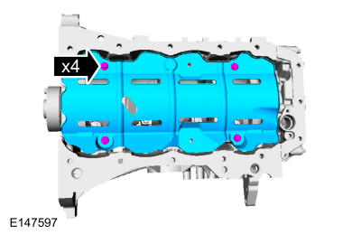
- Shim pads.
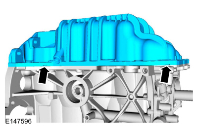
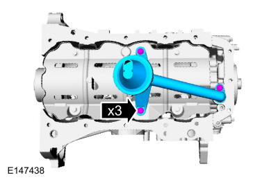
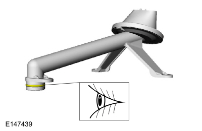
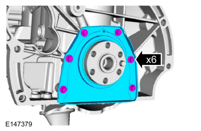
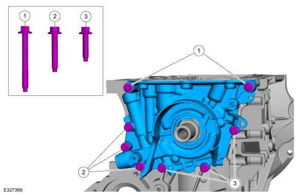
- Remove the two M6 x 55 mm bolts.
- Remove the three M6 x 35 mm bolts.
- Unscrew the three M6 x 25 mm bolts and remove the oil pump.
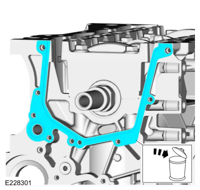
- Remove and discard the oil pump gasket.
- Clean the oil pump bolt holes with Motorcraft® Metal Brake Parts Cleaner to remove all oil residue.
Material: Motorcraft® Metal Brake Parts Cleaner / PM-4-A, PM-4-B, APM-4-C
- Use compressed air to remove brake cleaner or oil from the oil pump bolt holes.
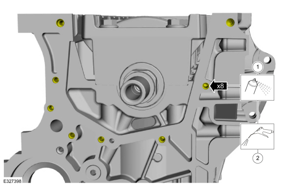
- Clean the oil pump bolt holes with Motorcraft® Metal Brake Parts Cleaner to remove all oil residue.
- Clean the specified component with an abrasive pad.
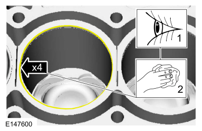
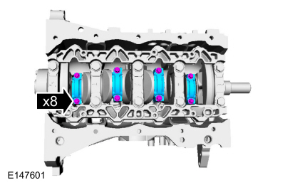
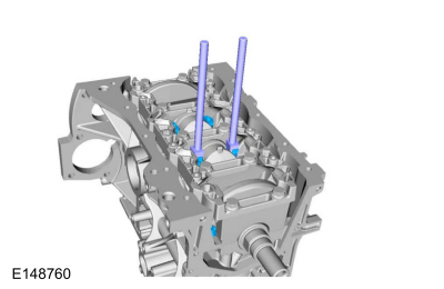
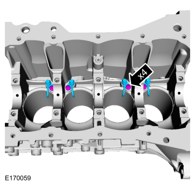
- Repeat with the connecting rod installation tool until all piston/connecting rod assemblies are removed from the cylinder block.
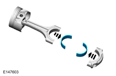
- Refer to: Piston Inspection (303-00 Engine System - General Information, General Procedures).
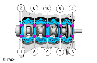
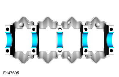
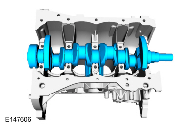
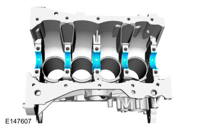
Test yourself
A quick Ford Fiesta quiz: every answer comes with an explanation and a link to the manual page.