Engine
Engine - Installation
In this manual: Engine
69steps
~429min
5/5difficulty
3special tools
Done 0 of 69
Special Service Tools / General Equipment
 |
205-461 Protector, Differential Seal (Pair) TKIT-2000AP-FLM/LM TKIT-2002-F/FM |
 |
300-OTC1585AE Powertrain Lift |
 |
300-OTC1819E Floor Crane 2200 lb, Folding |
 |
303-1502 Engine Lifting Device TKIT-2012A-FL TKIT-2012A-RYAD |
 |
303-476 (T94P-9472-A) Socket, Exhaust Gas Oxygen Sensor TKIT-1994-LM/M TKIT-1994-F TKIT-1994-FLM/FM |
| Cable Ties | |
| Hose Clamp Removal/Installation Tool | |
| Wood block | |
Materials
| Name | Specification |
|---|---|
| Motorcraft® 4x4 High-Temperature Front Axle and Hub Bearing Grease XG-11 |
WSS-M1C267-A1 |
| Engine Oil — SAE 5W-20 — Semi-Synthetic Engine Oil XO-5W20-Q1SP |
WSS-M2C945-B1 |
| Motorcraft® High-Temperature Nickel Anti-Seize Lubricant XL-2 |
- |
- Lubricate the torque converter hub guide with multi-purpose grease.
Material: Motorcraft® 4x4 Front Axle and Hub Bearing High Temperature Grease / XG-11 (WSS-M1C267-A1)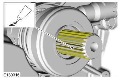
- Align the engine with the transmission and install the bolt.
Torque: 35 lb-ft (48 N·m)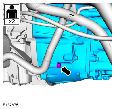
- Install the engine to the transmission bolts.
Torque: 35 lb-ft (48 N·m)
- Install the engine to the transmission bolts.
Torque: 35 lb-ft (48 N·m)
- Install the engine on the stand.
Install the special service tool: 300-OTC1585AE Powertrain Lift.
Use common shop equipment: wooden block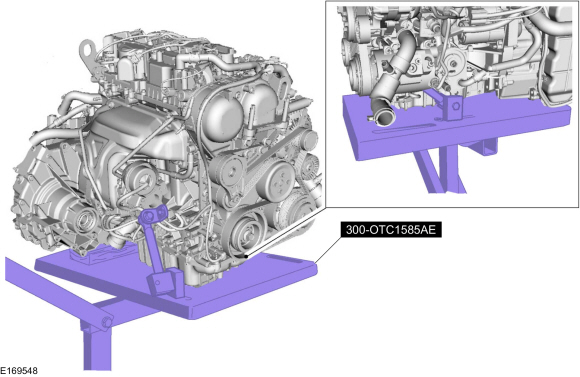
- Remove the engine floor crane.
Remove the special service tool: 300-OTC1819E 2200 lb Floor Crane, Folding.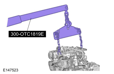
- Remove the special service tool: 303-1502 Engine Lifting Device.
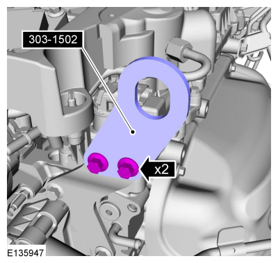
- Install the coolant hose and secure the clip.

- Install the starter and bolts, install the electrical connection and install the starter solenoid terminal nut.
Torque: 89 lb-in (10 N·m)
- Install the nut for the solenoid terminal wiring electrical connection.
Torque: 89 lb-in (10 N·m)
- Position the ground cable and install the bolt.
Torque: 35 lb-ft (48 N·m)
- Install the coolant hose and clamps, connect the electrical connector and the harness retainer.
Use common shop equipment: hose clamp removal/installation tool.
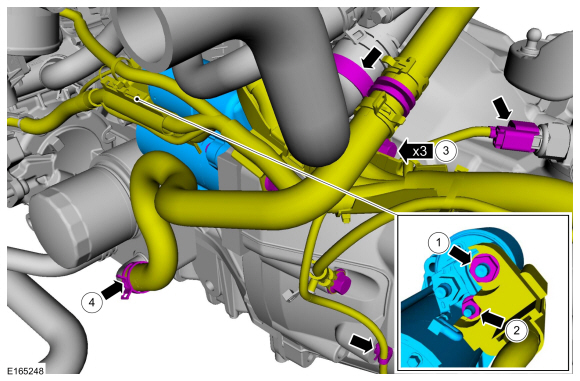
- Install the starter and bolts, install the electrical connection and install the starter solenoid terminal nut.
- Install the bracket and bolts.
Torque: 177 lb-in (20 N·m)
- Install a new catalytic converter gasket and tighten the bolts.
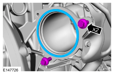
- Install the catalytic converter onto the loosely installed bolts, install the remaining bolt, then tighten the bolts in the sequence shown.
Torque: 18 lb-ft (25 N·m)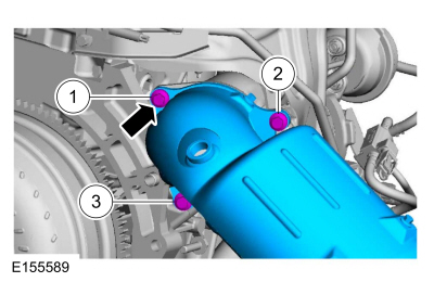
- Install the catalytic converter mounting bracket and nuts.
Torque: 18 lb-ft (24 N·m)
- Install the heat shield, install the clamp and install the bolts.
Torque: 89 lb-in (10 N·m)
- Using the special service tool, install the HO2S sensor. Attach the wiring harness retainer.
Use special service tool: 303-476 (T94P-9472-A) Exhaust Gas Oxygen Sensor Socket.
Material: Motorcraft® High Temperature Nickel Anti-Seize Lubricant / XL-2
Torque: 35 lb-ft (48 N·m)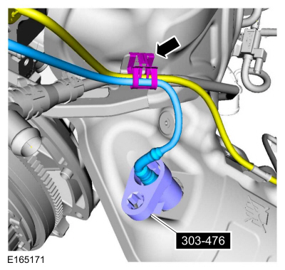
- Connect the electrical connectors.
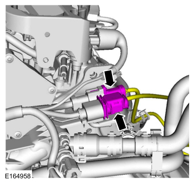
- Tighten the engine mount studs.
Torque: 89 lb-in (10 N·m)
- Using the powertrain lift, raise the powertrain into the vehicle.

- Install the engine mount and nuts.
Torque: 59 lb-ft (80 N·m)
- Install the bolts.
Torque: 35 lb-ft (48 N·m)

- Install the engine mount and nuts.
- Install the nuts.
Torque: 92 lb-ft (125 N·m)
- Using a new gasket, install the muffler inlet pipe and install the nuts.
Torque: 35 lb-ft (48 N·m)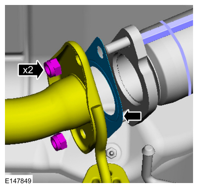
- Remove the cable ties.
Use general equipment: cable ties
- Install the bracket and bolts.
Torque: 35 lb-ft (48 N·m)
- Clean and inspect the left half shaft internal splines and mating surfaces.

- Replace the left half shaft seal.
Refer to: Left Half Shaft Seal (308-03B Manual Transmission - 6-Speed Manual Transmission - B6, Removal and Installation). - Install a new left half shaft retaining ring.
Remove special service tool: 205-461 Protector, Differential Seal (Pair).
- Install the half shaft. Pull the half shaft outward to make sure the retaining ring is locked.

- Clean and inspect the right half shaft internal splines and mating surfaces.

- Replace the right half shaft seal.
Refer to: Right Half Shaft Seal (308-03B Manual Transmission - 6-Speed Manual Transmission - B6, Removal and Installation). - Remove the special tool before fully installing the right half shaft.
Remove special service tool: 205-461 Protector, Differential Seal (Pair).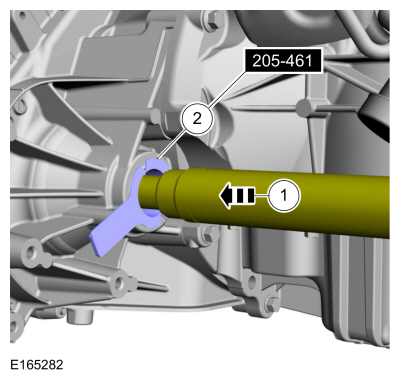
- Install the right half shaft.

- Install a new half shaft bearing retainer lock and nuts.
Torque:
Stage 1: 44 lb-in (5 N·m)
Stage 2: 18 lb-ft (24 N·m)
- Lubricate and install the engine oil filter.
Material: Engine Oil - SAE 5W-20 - Synthetic Engine Oil / WSS-M2C945-B1 (ESP-M2C945-B1)
Torque: 128 lb-in (14.5 N·m)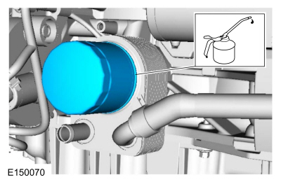
- Install the front subframe.
Refer to: Front Subframe (502-00 Uni-Body, Subframe and Mounting System, Removal and Installation). - Install the CAC outlet tube and tighten the clamps.
Torque: 44 lb-in (5 N·m)
- Install the nuts.
Torque: 97 lb-in (11 N·m)
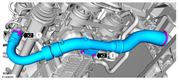
- Install the CAC outlet tube and tighten the clamps.
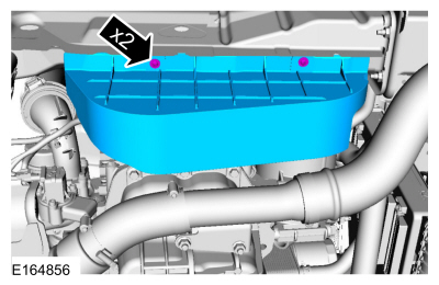
- Install the shield and clips.
- Install the CAC outlet pipe and nut.
Torque: 97 lb-in (11 N·m)
- Tighten the clamp and connect the electrical connector.
Torque: 44 lb-in (5 N·m)
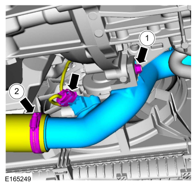
- Install the CAC outlet pipe and nut.
- Connect the throttle body hose and tighten the clamp, install the resonator assembly and clamps and connect the hose.
Use general equipment: hose clamp removal/installation tool.
Torque: 44 lb-in (5 N·m)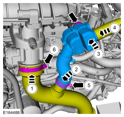
- Install the coolant recovery reservoir.
Refer to: Coolant Recovery Reservoir (303-03B Engine Cooling - 1.6 L EcoBoost (132 kW/180 L PS) - Sigma, Removal and Installation). - Using a new O-ring, connect the A/C line and install the nut.
Torque: 133 lb-in (15 N·m)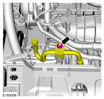
- Using a new O-ring, connect the A/C line and install the nut.
Torque: 133 lb-in (15 N·m)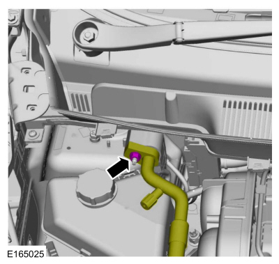
- Connect the shift selector cables to the shift selector levers.
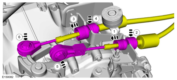
- Adjust the shift cable.
Refer to: Shift Cable Adjustment - 6-Speed Manual Transmission - B6 (308-06 Manual Transmission External Controls - 5-Speed Manual Transmission Transaxle - B5/IB5/6-Speed Manual Transmission - B6, General Procedures). - Connect the clutch master cylinder fluid supply tube.

- Connect the tube to the retaining clip.

- Connect the heater hoses.
Use general equipment: hose clamp removal/installation tool.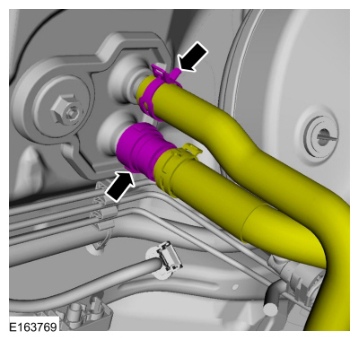
- Connect the coolant tube and secure the retainer.
Use general equipment: hose clamp removal/installation tool.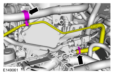
- Install the fuel vapor tube assembly. Connect the quick-connect fittings and electrical connector.

- Early production vehicles, connect the fuel tube connection.
Refer to: Quick-Connect Coupling (310-00B Fuel System - General Information). Information - 1.6 L EcoBoost (132 kW/180 L hp) - Sigma, General Procedures).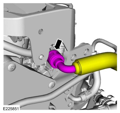
- Late production vehicles, connect the fuel tube connection.
Refer to: Spring-Lock Couplings (310-00B Fuel System - General Information). Information - 1.6 L EcoBoost (132 kW/180 L hp) - Sigma, General Procedures).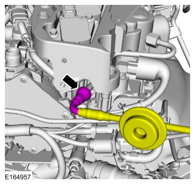
- Install the coolant hose and clamp.
Use general equipment: hose clamp removal/installation tool.
- Install the bracket and nuts.
Torque: 89 lb-in (10 N·m)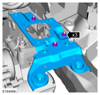
- Position the wiring harness and install the retainers.

- Position the wiring harness and install the retainers.
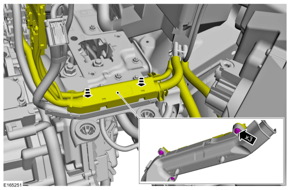
- Position the wiring harness and secure the retainers.
- Position the ground wire and install the bolt.
Torque: 115 lb-in (13 N·m)
- Connect the electrical connector.
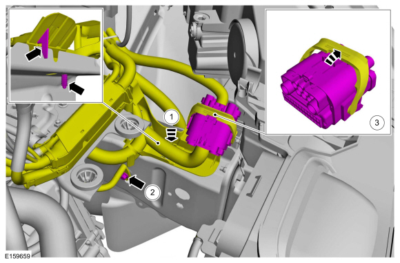
- Install the wire and nut.
Torque: 44 lb-in (5 N·m)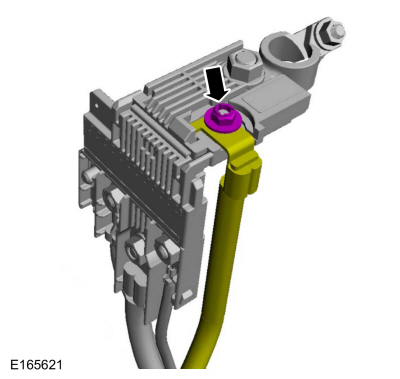
- Install the battery terminal cover.

- Install the battery tray.
Refer to: Battery Compartment - 1.6 L EcoBoost (132 kW/180 L hp) - Sigma (414-01 Battery, Mounting and Cables, Removal and Installation). - Install the air intake tube, engine cover stud and nut.
Torque: 44 lb-in (5 N·m)
- Tighten the clamp. Connect the crankcase vent tube coupling.
Torque: 44 lb-in (5 N·m)
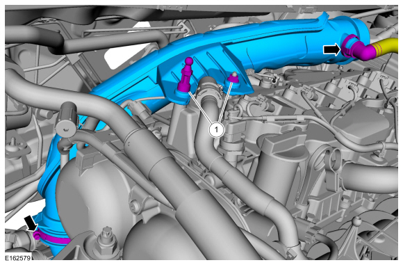
- Install the air intake tube, engine cover stud and nut.
- Install the air cleaner outlet tube and tighten the clamp. Connect the quick-connect coupling.
Torque: 44 lb-in (5 N·m)
- Install the air cleaner.
Refer to: Air Cleaner (303-12B Intake Air Distribution and Filtering - 1.6 L EcoBoost (132 kW/180 L hp) - Sigma, Removal and Installation). - Connect the vacuum pump inlet tube coupling.
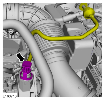
- Fill the engine with clean engine oil.
Material: Engine Oil - SAE 5W-20 - Synthetic Engine Oil / XO-5W20-Q1SP (WSS-M2C945-B1) - Install the engine outer cover.

- Fill the cooling system.
Refer to: Engine Cooling System Draining, Vacuum Filling and Bleeding (303-03B Engine Cooling - 1.6 L EcoBoost (132 kW/180 L hp) - Sigma, General Procedures). - Fill the air conditioning system.
Refer to: Air Conditioning (A/C) System Recovery, Evacuation and Charging (412-00 Climate Control System - General Information). - Fill the transmission fluid.
Refer to: Transmission Draining and Filling (308-03B Owner's Manual). Transmission - 6-Speed Manual Transmission - B6, General Procedures). - Bleed the clutch hydraulic system.
Refer to: Clutch Bleeding (308-02 Clutch Controls - 5-Speed Manual Transmission - B5/IB5/6-Speed Manual Transmission - B6, General Information Procedures). - After completing the repair, perform the Misfire Monitor Neutral Profile Relearn procedure.
Test yourself
A quick Ford Fiesta quiz: every answer comes with an explanation and a link to the manual page.
Was this page helpful?