Timing Belt. Removal and Installation
Special Service Tools / General Equipment
 |
303-1097 Locking Tool, Variable Camshaft Timing Oil Control Valve TKIT-2010B-FLM TKIT-2010B-RYAD |
 |
303-1550 Alignment Tool, Crankshaft Damper TKIT-2012A-FL TKIT-2012A-RYAD |
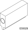 |
303-393-02 Adapter, 303-393 TKIT-2012A-FL TKIT-2012A-RHD |
 |
303-393A Flywheel Locking Tool TKIT-2012A-FL TKIT-2012A-RHD |
 |
303-748 Crankshaft Locking Tool TKIT-2010B-FLM TKIT-2010B-RHD |
| Floor Jack | |
| Wood block | |
Removal
NOTICE: Do not loosen or remove the crankshaft pulley bolt without first installing the special tools. The crankshaft pulley and crankshaft sprocket are not engaged with the crankshaft. Before any repair that requires loosening or removing the crankshaft pulley bolt, the crankshaft and camshafts must be locked with the special service tools, otherwise serious engine damage may occur.
- Position the vehicle in NEUTRAL on the lift.
Refer to: Jacking and Lifting - Overview (100-02 Jacking and Lifting, Description and Operation). - Remove the coolant recovery reservoir.
Refer to: Coolant Recovery Reservoir (303-03B Engine Cooling - 1.6 L EcoBoost (132 kW/180 L PS) - Sigma, Removal and Installation). - Remove the engine appearance cover.

- Disconnect the EVAP tube from the air cleaner outlet pipe.
- Loosen the clamps and remove the air cleaner outlet pipe.
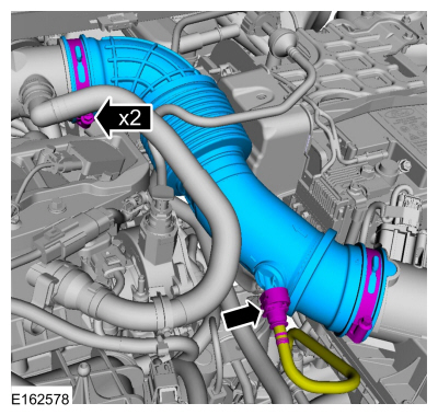
NOTICE: Whenever turbocharger air intake system components are removed, always cover the open ports to protect against debris. This is important to prevent foreign material from entering the system. Turbocharger compressor blades can be damaged by even small particles. All components must be inspected and cleaned, if necessary, before installation or reassembly.
- Remove the brackets.
- Disconnect the crankcase ventilation tube from the turbocharger inlet pipe, loosen the clamp and remove the turbocharger inlet pipe.

- Loosen the coolant pump pulley bolts.

- Remove the RH front wheel and tire.
Refer to: Wheels and Tires (204-04A Wheels and Tires, Removal and Installation). - Remove the clips and the shield.

- Remove the nuts and discard the axle shaft bracket.

- Remove the bolts and set the bracket aside.

- Remove the engine plug bolt.

- Remove the following components:
- Remove the starter.
Refer to: Starter (303-06B — 1.6 L EcoBoost (132 kW/180 L PS) — Sigma, Removal and Installation). - Remove the generator.
Refer to: Generator - 1.6 L EcoBoost (132 kW/180 L PS) - Sigma (414-02 Generator and Regulator, Removal and Installation).
- Remove the starter.
- Using a jack and a wood block, support the engine.
Use general equipment: jack stand
Use general equipment: wood block
- Remove the nuts.
- Remove the bolts and the engine mount.

- Remove the bolts and remove the tensioner and accessory drive belt.
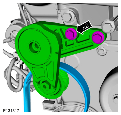
- Remove the front engine cover stud.
- Disengage the cover from the retainer and open it.
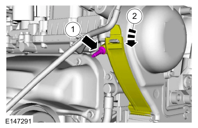
- Remove the coolant pump bolts and pulley.
- Remove the engine mount stud.
- Disconnect the wiring harness retainer.
- Remove the wiring harness mounting clip retainer.
- Disconnect the wiring harness retainer.
- Remove the bolts and the front engine cover.

- Disconnect the wiring harness clips.
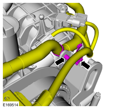
- Remove the bolts and the engine mount bracket.

- Rotate the VCT units until the timing marks are aligned at the 11 o'clock position.
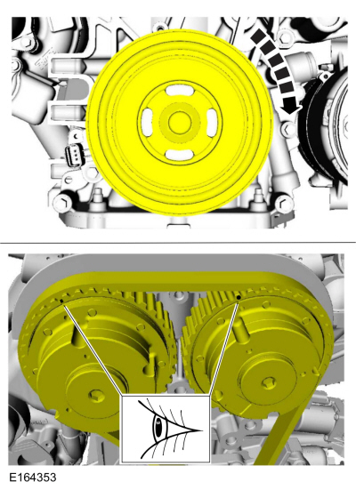
- Install the special service tool: 303-748 Crankshaft Locking Tool.

- Slowly rotate the crankshaft clockwise until the crankshaft balance weight contacts the crankshaft locking pin. The engine is now at TDC.

- Install the special service tools: 303-393-02 Adapter for 303-393, and 303-393A Locking Tool, Flywheel.

- Remove the crankshaft bolt and pulley.
- Discard the bolt.

- Install the special service tool: 303-1097 Locking Tool, Variable Camshaft Timing Oil Control Valve.

- Rotate the timing belt tensioner and install the retaining pin. Remove the timing belt.
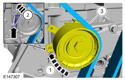
- Remove the crankshaft sprocket.

- Disconnect the electrical connector.
- Remove the bolt and the CKP sensor.

Installation
- Install the crankshaft sprocket.
- Install the timing belt.

- Remove the retaining pin.

- Install the crankshaft pulley.

- Install the special service tool: 303-1550 Alignment Tool, Crankshaft Damper.
- Rotate the crankshaft pulley to align the special tool:
Use the special service tool: 303-1550 Alignment Tool, Crankshaft Damper.
- At this stage, hand-tighten the bolt.
- Using a new bolt, hand-tighten it at this stage.
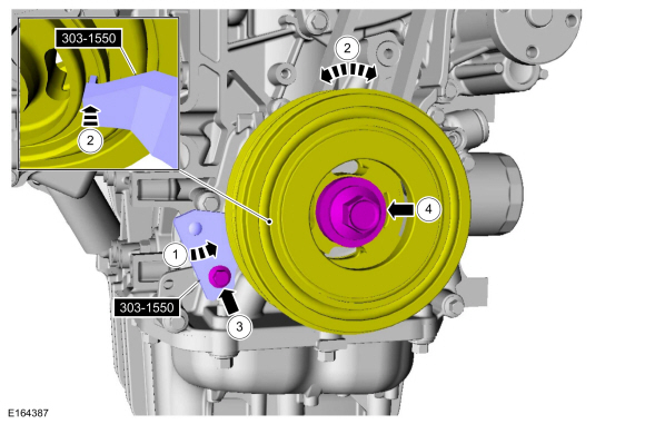
- Tighten the crankshaft pulley bolt.
Torque:
Stage 1: 74 lb-ft (100 N·m)
Stage 2: 90°
Stage 3: Wait 2 s
Stage 4: 15°
- Remove the special service tool: 303-1550 Alignment Tool, Crankshaft Damper.

- Remove the special service tool: 303-748 Crankshaft Locking Tool.

- Remove the special service tools: 303-393-02 Adapter for 303-393, and 303-393A Locking Tool, Flywheel.
- Remove the special service tool: 303-1097 Locking Tool, Variable Camshaft Timing Oil Control Valve.
- Rotate the crankshaft pulley approximately 1 3/4 turns.

- Install the special service tool: 303-748 Crankshaft Locking Tool.
- Slowly rotate the crankshaft clockwise until the crankshaft balance weight contacts the crankshaft locking pin. The engine is now at TDC.
- If the special tool cannot be installed, repeat the adjustment according to the previous steps.
Install the special service tool: 303-1097 Locking Tool, Variable Camshaft Timing Oil Control Valve. - Remove the special service tool: 303-1097 Locking Tool, Variable Camshaft Timing Oil Control Valve.
- Install the engine mount bracket and bolts.
Torque: 41 lb-ft (55 N·m) - Attach the wiring harness retainers.
- Install the front engine cover and bolts.
Torque: 89 lb-in (10 N·m)
- Install the engine mount stud, hand-tightening it.
- Install the coolant pulley and hand-tighten the bolts.
- Install the wiring harness mounting clip and retainer.
Torque: 71 lb-in (8 N·m)
- Secure the wiring harness retainer.
- Secure the wiring harness retainer.

- Install the front engine cover and bolts.
- Close the cover and attach the retainer.
- Install the front engine cover stud.
Torque: 89 lb-in (10 N·m)

- Install the accessory drive belt tensioner, belt and bolts.
Torque: 35 lb-ft (48 N·m) - Tighten the engine mount studs.
Torque: 89 lb-in (10 N·m)
- Install the engine mount and nuts.
Torque: 59 lb-ft (80 N·m)
- Install the bolts.
Torque: 35 lb-ft (48 N·m)
- Install the engine mount and nuts.
- Remove the jack and wood block.
Use general equipment: jack stand
Use general equipment: wood block - Remove the special service tool: 303-748 Crankshaft Locking Tool.
- Install the engine plug bolt.
Torque: 177 lb-in (20 N·m)
- Install the CKP sensor and bolt, connect the electrical connector.
Torque: 89 lb-in (10 N·m)
- Position the bracket and install the bolts.
Torque: 35 lb-ft (48 N·m) - Install the axle shaft bearing retainer and nuts.
Torque:
Stage 1: 44 lb-in (5 N·m)
Stage 2: 18 lb-ft (24 N·m)
- Install the following components:
- Install the generator.
Refer to: Generator — 1.6 L EcoBoost (132 kW/180 L PS) — Sigma (414-02 Generator and Regulator, Removal and Installation). - Install the starter motor.
Refer to: Starter Motor (303-06B Starting System — 1.6 L EcoBoost (132 kW/180 L PS) — Sigma, Removal and Installation).
- Install the generator.
- Install the shield and clips.
- Install the right front wheel and tire.
Refer to: Wheels and Tires (204-04A Wheels and Tires, Removal and Installation). - Tighten the coolant pump pulley bolts.
Torque: 18 lb-ft (24 N·m)
- Install the TC inlet pipe and brackets. Connect the crankcase ventilation tube.
Torque: 44 lb-in (5 N·m)
- Tighten the clamp.
Torque: 44 lb-in (5 N·m)
- Install the TC inlet pipe and brackets. Connect the crankcase ventilation tube.
- Install the air cleaner outlet pipe and tighten the clamps. Connect the EVAP tube to the air cleaner outlet pipe.
Torque: 44 lb-in (5 N·m) - Install the engine outer cover.
- Install the coolant recovery reservoir.
Refer to: Coolant Recovery Reservoir (303-03B Engine Cooling - 1.6 L EcoBoost (132 kW/180 L PS) - Sigma, Removal and Installation). - After completing the repair, perform the Misfire Monitor Neutral Profile Relearn procedure.
Test yourself
A quick Ford Fiesta quiz: every answer comes with an explanation and a link to the manual page.