Engine Control/Fuel System
Engine Control Module (ECM) Schematic diagrams
In this manual: Engine Control/Fuel System
~13min read
ECM Terminal And Input/Output signal
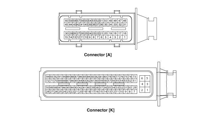
ECM Terminal Function
Connector [A]
| Pin No. | Description | Connected to |
| 1 | Injector (Cylinder #3) [Low] control | Injector (Cylinder #3) |
| 2 | Injector (Cylinder #4) [High] control | Injector (Cylinder #4) |
| 3 | Injector (Cylinder #4) [Low] control | Injector (Cylinder #4) |
| 4 | Engine speed signal output | Smart Key Control Module [Smart key type] / Immobilizer Module [Immobilizer type] |
| 5 | EGR Valve (Motor -) | Electric Exhaust Gas Recirculation (EGR) Valve |
| 6 | Sensor power (+5V) | Throttle Position Sensor (TPS) 1, 2 |
| 7 | Sensor power (+5V) | Electric Exhaust Gas Recirculation (EGR) Valve |
| 8 | Knock Sensor (KS) signal input | Knock Sensor (KS) |
| 9 | Camshaft Position Sensor (CMPS) [Bank 1/Exhaust] signal input | Camshaft Position Sensor (CMPS) [Bank 1 / Exhaust] |
| 10 | - | |
| 11 | Brake switch [Test] signal input | Brake switch |
| 12 | Brake switch [Lamp] signal input | Brake switch |
| 13 | - | |
| 14 | - | |
| 15 | - | |
| 16 | Injector (Cylinder #3) [High] control | Injector (Cylinder #3) |
| 17 | Injector (Cylinder #1) [High] control | Injector (Cylinder #1) |
| 18 | Injector (Cylinder #1) [Low] control | Injector (Cylinder #1) |
| 19 | - | |
| 20 | EGR Valve (Motor +) | Electric Exhaust Gas Recirculation (EGR) Valve |
| 21 | Sensor shield | Knock Sensor (KS) |
| 22 | Sensor ground (-) | Knock Sensor (KS) |
| 23 | - | |
| 24 | Sensor ground | Camshaft Position Sensor (CMPS) [Bank 1 / Exhaust] |
| 25 | - | |
| 26 | - | |
| 27 | - | |
| 28 | - | |
| 29 | - | |
| 30 | - | |
| 31 | Injector (Cylinder #2) [High] control | Injector (Cylinder #2) |
| 32 | - | |
| 33 | ETC Motor [-] control | ETC Motor |
| 34 | Sensor ground | Throttle Position Sensor (TPS) 1, 2 |
| 35 | Throttle Position Sensor (TPS) 1 signal input | Throttle Position Sensor (TPS) 1 |
| 36 | Sensor ground | Rail Pressure Sensor (RPS) |
| 37 | Rail Pressure Sensor (RPS) signal input | Rail Pressure Sensor (RPS) |
| 38 | - | |
| 39 | Camshaft Position Sensor (CMPS) [Bank 1/Intake] signal input | Camshaft Position Sensor (CMPS) [Bank 1/Intake] |
| 40 | - | |
| 41 | - | |
| 42 | - | |
| 43 | VS-/IP- (Virtual Ground) | Heated Oxygen Sensor [Bank 1/Sensor 1] |
| 44 | Rc (Compensative Resistance) | Heated Oxygen Sensor [Bank 1/Sensor 1] |
| 45 | Sensor ground | Heated Oxygen Sensor [Bank 1/Sensor 2] |
| 46 | Injector (Cylinder #2) [Low] control | Injector (Cylinder #2) |
| 47 | - | |
| 48 | ETC Motor [+] control | ETC Motor |
| 49 | - | |
| 50 | Throttle Position Sensor (TPS) 2 signal input | Throttle Position Sensor (TPS) 2 |
| 51 | Sensor power (+5V) | Rail Pressure Sensor (RPS) |
| 52 | Electric load signal input | Wiper Motor |
| 53 | Sensor ground | Camshaft Position Sensor (CMPS) [Bank 1/Intake] |
| 54 | Sensor ground | Electric Exhaust Gas Recirculation (EGR) Valve |
| 55 | EGR Valve (Feedback signal) | Electric Exhaust Gas Recirculation (EGR) Valve |
| 56 | - | |
| 57 | - | |
| 58 | VS+ (NERNST cell voltage) | Heated Oxygen Sensor [Bank 1/Sensor 1] |
| 59 | Rc/Rp (Pumping cell voltage) | Heated Oxygen Sensor [Bank 1/Sensor 1] |
| 60 | Heated Oxygen Sensor [Bank 1/Sensor 2] signal input | Heated Oxygen Sensor [Bank 1/Sensor 2] |
Connector [K]
| Pin No. | Description | Connected to |
| 1 | ECM Ground | Chassis ground |
| 2 | Battery power (B+) | Main Relay |
| 3 | ECM Ground | Chassis ground |
| 4 | Battery power (B+) | Main Relay |
| 5 | ECM Ground | Chassis ground |
| 6 | Battery power (B+) | Main Relay |
| 7 | Fuel Pressure Control Valve [High] control | Fuel Pressure Control Valve (FPCV) |
| 8 | - | |
| 9 | - | |
| 10 | Engine Coolant Sensor (ECTS) signal input [EGR cooler tube] | Engine Coolant Sensor (ECTS) [EGR cooler tube] |
| 11 | Sensor ground | Engine Coolant Sensor (ECTS) [EGR cooler tube] |
| 12 | Vehicle signal input | Active Hydraulic Boost (AHB) System |
| Smart key control module | ||
| 13 | - | |
| 14 | - | |
| 15 | Accelerator Position Sensor (APS) 2 signal input | Accelerator Position Sensor (APS) 2 |
| 16 | Sensor power (+5V) | Accelerator Position Sensor (APS) 2 |
| 17 | Sensor power (+5V) | Manifold Absolute Pressure Sensor (MAPS) & Intake Air Temperature Sensor (IATS) |
| 18 | Sensor power (+5V) | Accelerator Position Sensor (APS) 1 |
| 19 | Accelerator Position Sensor (APS) 1 signal input | Accelerator Position Sensor (APS) 1 |
| 20 | Sensor power (+5V) | Crankshaft Position Sensor Sensor (CKPS) |
| A/C Pressure Transducer (APT) | ||
| 21 | - | |
| 22 | - | |
| 23 | - | |
| 24 | Fuel pump relay control | Fuel pump relay |
| 25 | - | |
| 26 | - | |
| 27 | - | |
| 28 | - | |
| 29 | Fuel Pressure Control Valve [Low] control | Fuel Pressure Control Valve(FPCV) |
| 30 | A/C Pressure Transducer (APT) signal input | A/C Pressure Transducer (APT) |
| 31 | - | |
| 32 | Crankshaft Position Sensor Sensor (CKPS) signal input | Crankshaft Position Sensor Sensor (CKPS) |
| 33 | - | |
| 34 | - | |
| 35 | - | |
| 36 | - | |
| 37 | Sensor ground (-) | Accelerator Position Sensor (APS) 2 |
| 38 | Manifold Absolute Pressure Sensor (MAPS) signal input | Manifold Absolute Pressure Sensor (MAPS) & Intake Air Temperature Sensor (IATS) |
| 39 | Intake Air Temperature Sensor (IATS) signal input | Manifold Absolute Pressure Sensor (MAPS) & Intake Air Temperature Sensor (IATS) |
| 40 | Sensor ground (-) | Manifold Absolute Pressure Sensor (MAPS) & Intake Air Temperature Sensor (IATS) |
| 41 | Sensor ground (-) | Accelerator Position Sensor (APS) 1 |
| 42 | - | |
| 43 | - | |
| 44 | Mass Air Flow Sensor (MAFS) signal input | Mass Air Flow Sensor (MAFS) |
| 45 | Sensor ground (-) | Mass Air Flow Sensor (MAFS) |
| 46 | Main Relay control | Main Relay |
| 47 | Variable Force Solenoid (VFS) [Bank 1/ Intake] control | Variable Force Solenoid (VFS) [Bank 1/ Intake] |
| 48 | ||
| 49 | - | |
| 50 | - | |
| 51 | Battery power (B+) | Ignition Switch |
| 52 | - | |
| 53 | - | |
| 54 | Sensor ground (-) | Crankshaft Position Sensor Sensor (CKPS) |
| 55 | P-CAN [High] | Other control module, Data Link Connector (DLC), Multi-Purpose Check Connector |
| 56 | H-CAN [High] | Other control module, Data Link Connector (DLC), Multi-Purpose Check Connector |
| 57 | - | |
| 58 | Immobilizer communication line | Smart key control module |
| 59 | - | |
| 60 | Engine Coolant Sensor (ECTS) signal input [Water Temperature Control Assembly] | Engine Coolant Sensor (ECTS) [Water Temperature Control Assembly] |
| 61 | Sensor ground | Engine Coolant Sensor (ECTS) [Water Temperature Control Assembly] |
| 62 | ||
| 63 | - | |
| 64 | Ignition Coil (Cylinder #2) control | Ignition Coil (Cylinder #2) |
| 65 | Ignition Coil (Cylinder #3) control | Ignition Coil (Cylinder #3) |
| 66 | - | |
| 67 | - | |
| 68 | Cooling fan relay control | Cooling Fan Relay |
| 69 | - | |
| 70 | CVVT Oil Control Valve (OCV) (OCV) [Bank 1/ Exhaust] control | CVVT Oil Control Valve (OCV) (OCV) [Bank 1/ Exhaust] |
| 71 | - | |
| 72 | - | |
| 73 | Battery power (B+) | Battery |
| 74 | - | |
| 75 | Sensor ground (-) | A/C Pressure Transducer (APT) |
| 76 | Local Interconnect Network (LIN) Serial Bus Line | Battery Sensor |
| 77 | P-CAN [Low] | Other control module, Data Link Connector (DLC), Multi-Purpose Check Connector |
| 78 | H-CAN [Low] | Other control module, Data Link Connector (DLC), Multi-Purpose Check Connector |
| 79 | - | |
| 80 | - | |
| 81 | - | |
| 82 | - | |
| 83 | - | |
| 84 | - | |
| 85 | - | |
| 86 | Ignition Coil (Cylinder #4) control | Ignition Coil (Cylinder #4) |
| 87 | Ignition Coil (Cylinder #1) control | Ignition Coil (Cylinder #1) |
| 88 | - | |
| 89 | - | |
| 90 | - | |
| 91 | Heated Oxygen Sensor (HO2S) [Bank 1/Sensor1] Heater control | Heated Oxygen Sensor (HO2S) [Bank 1/Sensor 1] |
| 92 | Heated Oxygen Sensor (HO2S) [Bank 1/Sensor2] Heater control | Heated Oxygen Sensor (HO2S) [Bank 1/Sensor 1] |
| 93 | Purge Control Solenoid Valve (PCSV) control | Purge Control Solenoid Valve (PCSV) |
| 94 | - |
ECM Terminal Input/Output Signal
Connector [A]
| Pin No. | Description | Condition | Type | Level |
| 1 | Injector (Cylinder #3) [Low] control | Relay OFF | DC Voltage | 71V |
| Relay ON | Max. 1.0V | |||
| 2 | Injector (Cylinder #4) [High] control | Relay OFF | DC Voltage | 71V |
| Relay ON | Max. 1.0V | |||
| 3 | Injector (Cylinder #4) [Low] control | Relay OFF | DC Voltage | 71V |
| Relay ON | Max. 1.0V | |||
| 4 | Engine speed signal output | Idle | Pulse | High: Battery Voltage |
| Low: Max. 0.6V | ||||
| 5 | EGR Valve (Motor -) | |||
| 6 | Sensor power (+5V) | IG OFF | DC Voltage | Max. 0.5V |
| IG ON | 4.9 - 5.1V | |||
| 7 | Sensor power (+5V) | IG OFF | DC Voltage | Max. 50mV |
| IG ON | 4.9 - 5.1V | |||
| 8 | Knock Sensor (KS) signal input | Knocking | Variable Frequency |
-0.3 - 0.3V |
| Normal | 0V | |||
| 9 | Camshaft Position Sensor (CMPS) [Bank 1/Exhaust] signal input | Engine Run | Pulse | High: 4.5 - 5.5V |
| Low: -0.3 - 0.5V | ||||
| Frequency: 7Hz (Idle), 25Hz (3,000rpm) | ||||
| 10 | - | |||
| 11 | Brake switch [Test] signal input | Brake OFF | DC Voltage | Battery Voltage (B+) |
| Brake ON | Max. 50mV | |||
| 12 | Brake switch [Lamp] signal input | Brake OFF | DC Voltage | Max. 50mV |
| Brake ON | Battery Voltage (B+) | |||
| 13 | - | |||
| 14 | - | |||
| 15 | - | |||
| 16 | Injector (Cylinder #3) [High] control | Relay ON/OFF | DC Voltage | 71V |
| 17 | Injector (Cylinder #1) [High] control | Relay ON/OFF | DC Voltage | 71V |
| 18 | Injector (Cylinder #1) [Low] control | Relay OFF | DC Voltage | 71V |
| Relay ON | Max. 1.0V | |||
| 19 | - | |||
| 20 | EGR Valve (Motor +) | |||
| 21 | Sensor shield | Idle | DC Voltage | Max. 50mV |
| 22 | Sensor ground (-) | Idle | DC Voltage | Max. 50mV |
| 23 | - | |||
| 24 | Sensor ground (-) | Idle | DC Voltage | Max. 50mV |
| 25 | - | |||
| 26 | - | |||
| 27 | - | |||
| 28 | - | |||
| 29 | - | |||
| 30 | - | |||
| 31 | Injector (Cylinder #2) [High] control | Relay ON/OFF | DC Voltage | 71V |
| 32 | - | |||
| 33 | ETC Motor [-] control | |||
| 34 | Sensor ground (-) | Idle | DC Voltage | Max. 50mV |
| 35 | Throttle Position Sensor (TPS) 1 signal input | C.T | Analog | 0.3 - 0.9V |
| W.O.T | 1.5 - 3.0V | |||
| 36 | Sensor ground (-) | Idle | DC Voltage | Max. 50mV |
| 37 | Rail Pressure Sensor (RPS) signal input | Idle | Analog | -0.3 - 5.2V |
| 38 | - | |||
| 39 | Camshaft Position Sensor (CMPS) [Bank 1/Intake] signal input | Engine Run | Pulse | High: 4.5 - 5.5V |
| Low: -0.3 - 0.5V | ||||
| Frequency: 7Hz (Idle), 25Hz (3,000rpm) | ||||
| 40 | - | |||
| 41 | - | |||
| 42 | - | |||
| 43 | VS-/IP- (Common Ground for VS, IP) | Idle | Analog | Reference for V_IP, V_N |
| 44 | Rc (Compensative Resistance) | Idle | Analog | │Rc-Rc/Rp│<±0.1V |
| 45 | Sensor ground | Idle | DC Voltage | Max. 50mV |
| 46 | Injector (Cylinder #2) [Low] control | Relay OFF | DC Voltage | 71V |
| Relay ON | Max. 1.0V | |||
| 47 | - | |||
| 48 | ETC Motor [+] control | Engine Run | Pulse | High: Battery Voltage (B+) |
| Low: Max.1.0V | ||||
| 49 | - | |||
| 50 | Throttle Position Sensor (TPS) 2 signal input | C.T | Analog | 4.2 - 5.0V |
| W.O.T | 3.3 - 3.8V | |||
| 51 | Sensor power (+5V) | IG OFF | DC Voltage | Max. 50mV |
| IG ON | 4.9 - 5.1V | |||
| 52 | Electric load signal input | Lamp OFF | DC Voltage | Battery Voltage (B+) |
| Lamp ON | Max. 50mV | |||
| 53 | Sensor ground | Idle | DC Voltage | Max. 50mV |
| 54 | Sensor ground | Idle | DC Voltage | Max. 50mV |
| 55 | EGR Valve (Feedback signal) | |||
| 56 | - | |||
| 57 | - | |||
| 58 | VS+ (NERNST cell voltage) | Idle | Analog | Normal: 450±50mV |
| Rich: Max. Normal+150mV | ||||
| Lean: Min. Normal-150mV | ||||
| 59 | Rc/Rp (Pumping cell voltage) | Idle | Analog | Normal: 450±50mV |
| Rich: Max. Normal+150mV | ||||
| Lean: Min. Normal-150mV | ||||
| 60 | Heated Oxygen Sensor [Bank 1/Sensor 2] signal input | Idle | DC Voltage | Rich: 0.6 - 1.0V |
| Lean: Max. 0.4V |
Connector [K]
| Pin No. | Description | Condition | Type | Level |
| 1 | ECM Ground (-) | Idle | DC Voltage | -0.3 - 0.5V |
| 2 | Battery power (B+) | IG OFF | DC Voltage | Max. 1.0V |
| IG ON | Battery Voltage (B+) | |||
| 3 | ECM Ground (-) | Idle | DC Voltage | -0.3 - 0.5V |
| 4 | Battery power (B+) | IG OFF | DC Voltage | Max. 1.0V |
| IG ON | Battery Voltage (B+) | |||
| 5 | ECM Ground (-) | Idle | DC Voltage | -0.3 - 0.5V |
| 6 | Battery power (B+) | IG OFF | DC Voltage | Max. 1.0V |
| IG ON | Battery Voltage (B+) | |||
| 7 | Fuel Pressure Control Valve (FPCV)[High] control | Engine Run | PWM | 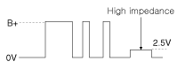 |
| 8 | - | |||
| 9 | - | |||
| 10 | Engine Coolant Sensor (ECTS) signal input [EGR cooler tube] | Idle | Analog | 0.5 - 4.5V |
| (Idle: 1.02V) | ||||
| 11 | Sensor ground | Idle | DC Voltage | Max. 50mV |
| 12 | Vehicle signal input | |||
| 13 | - | |||
| 14 | - | |||
| 15 | Accelerator Position Sensor (APS) 2 signal input | C.T | Analog | Max. 1.0V |
| W.O.T | 1.5 - 3.0V | |||
| 16 | Sensor power (+5V) | IG OFF | DC Voltage | Max. 50mV |
| IG ON | 4.9 - 5.1V | |||
| 17 | Sensor power (+5V) | IG OFF | DC Voltage | Max. 50mV |
| IG ON | 4.9 - 5.1V | |||
| 18 | Sensor power (+5V) | IG OFF | DC Voltage | Max. 50mV |
| IG ON | 4.9 - 5.1V | |||
| 19 | Accelerator Position Sensor (APS) 1 signal input | C.T | Analog | Max. 1.0V |
| W.O.T | Min. 4.0V | |||
| 20 | Sensor power (+5V) | IG OFF | DC Voltage | Max. 50mV |
| IG ON | 4.9 - 5.1V | |||
| 21 | - | |||
| 22 | - | |||
| 23 | - | |||
| 24 | Fuel pump relay control | Relay OFF | DC Voltage | Battery Voltage (B+) |
| Relay ON | -0.3 - 1.2V | |||
| 25 | - | |||
| 26 | - | |||
| 27 | - | |||
| 28 | - | |||
| 29 | Fuel Pressure Control Valve [Low] control | Engine Run | PWM | 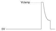 |
| 30 | A/C Pressure Transducer (APT) signal input | A/C ON | Analog | 0.348 - 4.63 V |
| 31 | - | |||
| 32 | Crankshaft Position Sensor Sensor (CKPS) signal input | Engine Run | Pulse | High: 4.5 - 5.5V |
| Low: - 0.3 - 0.5V | ||||
| Frequency: 850Hz (Idle), 3,000Hz (3,000rpm) | ||||
| 33 | - | |||
| 34 | - | |||
| 35 | - | |||
| 36 | - | |||
| 37 | Sensor ground (-) | Idle | DC Voltage | Max. 50mV |
| 38 | Manifold Absolute Pressure Sensor (MAPS) signal input | Idle | Analog | 0.8 - 1.6V (Idle: 1.37V) |
| 39 | Intake Temperature Sensor (IATS) signal input | Idle | Analog | 0 - 5.0V (Idle: 2.55V) |
| 40 | Sensor ground (-) | Idle | DC Voltage | Max. 50mV |
| 41 | Sensor ground (-) | Idle | DC Voltage | Max. 50mV |
| 42 | - | |||
| 43 | - | |||
| 44 | Mass Air Flow Sensor (MAFS) signal input | |||
| 45 | Sensor ground | Idle | DC Voltage | Max. 50mV |
| 46 | Main Relay control | Relay OFF | DC Voltage | Battery Voltage (B+) |
| Relay ON | -0.3 - 1.2V | |||
| 47 | Variable Force Solenoid (VFS) [Bank 1/ Intake] control | |||
| 48 | - | |||
| 49 | - | |||
| 50 | - | |||
| 51 | Battery power (B+) | IG OFF | DC Voltage | Max. 1.0V |
| IG ON | Battery Voltage (B+) | |||
| 52 | - | |||
| 53 | - | |||
| 54 | Sensor ground (-) | Idle | DC Voltage | Max. 50mV |
| 55 | P-CAN [High] | Recessive | Pulse | 2.0 - 3.0V |
| Dominant | 2.75 - 4.5V | |||
| 56 | H-CAN [High] | Recessive | Pulse | 2.0 - 3.0V |
| Dominant | 2.75 - 4.5V | |||
| 57 | - | |||
| 58 | Immobilizer communication line | |||
| 59 | - | |||
| 60 | Engine Coolant Sensor (ECTS) signal input [Water Temperature Control Assembly] | |||
| 61 | Sensor ground | Idle | DC Voltage | Max. 50mV |
| 62 | ||||
| 63 | - | |||
| 64 | Ignition Coil (Cylinder #2) control | Engine Run | Pulse | Vpeak = 360 - 440V |
| 125 | ||||
| 65 | Ignition Coil (Cylinder #3) control | Engine Run | Pulse | Vpeak = 360 - 440V |
| 125 | ||||
| 66 | - | |||
| 67 | - | |||
| 68 | Cooling fan relay control | |||
| 69 | - | |||
| 70 | CVVT Oil Control Valve (OCV) (OCV) [Bank 1/ Exhaust] control | Idle | Pulse | High: Battery Voltage (B+) |
| Low: -0.3 - 1.0V | ||||
| Frequency: 300Hz | ||||
| 71 | - | |||
| 72 | - | |||
| 73 | Battery power (B+) | IG OFF | DC Voltage | Max. 1.0V |
| IG ON | Battery Voltage (B+) | |||
| 74 | - | |||
| 75 | Sensor ground (-) | Idle | DC Voltage | Max. 50mV |
| 76 | Local Interconnect Network (LIN) Serial Bus Line | |||
| 77 | P-CAN [Low] | Recessive | Pulse | 2.0 - 3.0V |
| Dominant | 2.75 - 4.5V | |||
| 78 | H-CAN [Low] | Recessive | Pulse | 2.0 - 3.0V |
| Dominant | 2.75 - 4.5V | |||
| 79 | - | |||
| 80 | - | |||
| 81 | - | |||
| 82 | - | |||
| 83 | ||||
| 84 | Sensor ground (-) | Idle | DC Voltage | Max. 50mV |
| 85 | - | |||
| 86 | Ignition Coil (Cylinder #4) control | Engine Run | Pulse | Vpeak = 360 - 440V |
| 125 | ||||
| 87 | Ignition Coil (Cylinder #1) control | Engine Run | Pulse | Vpeak = 360 - 440V |
| 125 | ||||
| 88 | - | |||
| 89 | - | |||
| 90 | - | |||
| 91 | Heated Oxygen Sensor (HO2S) [Bank 1/Sensor1] Heater control | Engine Run | Pulse | High: Battery Voltage (B+) |
| Low: -0.3 - 1.0V | ||||
| Frequency: 8 - 10Hz | ||||
| Duty: 0 - 100% | ||||
| 92 | Heated Oxygen Sensor (HO2S) [Bank 1/Sensor2] Heater control | Engine Run | Pulse | High: Battery Voltage (B+) |
| Low: -0.3 - 1.0V | ||||
| Frequency: 8 - 10Hz | ||||
| Duty: 0 - 100% | ||||
| 93 | Purge Control Solenoid Valve (PCSV) control | Inactive Active | Pulse | High: Battery Voltage (B+) |
| Low: Max. 1.0V | ||||
| Vpeak: 42.0 - 60.0V | ||||
| Frequency: 20Hz | ||||
| 94 | - |
Was this page helpful?