Injector Repair procedures
Inspection
Switch "OFF" the ignition.
Disconnect the injector connector.
Measure resistance between the injector terminals 1 and 2.
Check that the resistance is within the specification.
Specification: 1.425 - 1.575 Ω [20 °C]
Removal
Release the residual pressure in fuel line.
(Refer to the Fuel Delivery System - "Release Residual Pressure in Fuel Line")
Switch "OFF" the ignition and disconnect the negative (-) battery terminal.
Remove the intake manifold.
(Refer to Engine Mechanical System - “Intake Manifold”)
Remove the delivery pipe & injector assembly.
(Refer to Fuel Delivery System - "Delivery Pipe")
Remove the connector (A) and the fixing clip (B), and then separate the injector from the delivery pipe.

Installation

Combustion seal
Rubber washer
Support disc
O-ring
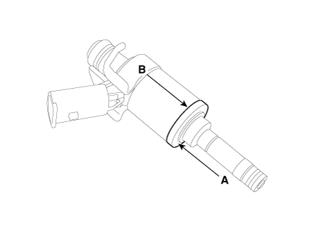
Install in the reverse order of removal.
Replacement
The injector combustion seal should be replaced with a new one to prevent leakage after removing the injector.
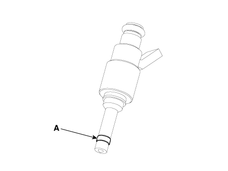
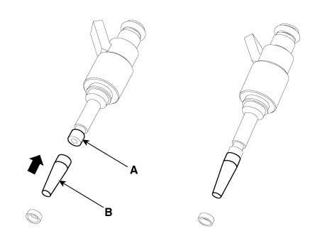
Remove the combustion seal (A) with a wire cutter.
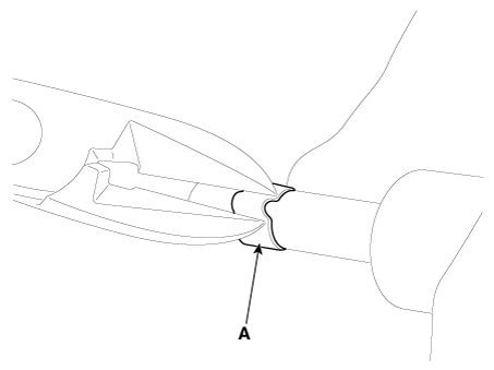
Before assembling the sealing ring, clean the groove with a clean cloth.
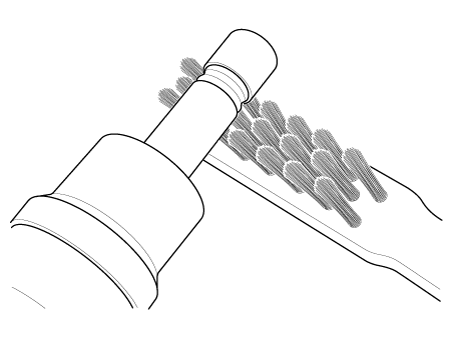
Any coking of the injector sealing surface must be carefully removed with a brass-wire brush.
Place the seal installation guide (B) (SST No.: 09353-2B000) on the tip of the injector without damaging the injector tip (A).
Push the sealing ring (C) with thumb and index finger over the conical assembly tool until it snaps into the groove.
The complete assembly must not take longer than 2 to 3 seconds.
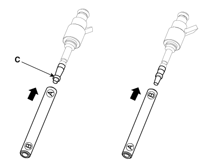
To size the sealing ring the injector is first introduced into the sizing tool (A) (SST No.: 09353-2B000) and then pressed and at the same time rotated 180° into the sizing tool.
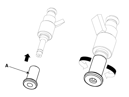
Pull the injector out of the sizing tool by turning it in the reverse direction of the press-in process.
Check the combustion seal (A) installation.