Engine Mechanical System
Components and Components Location
In this manual: Engine Mechanical System
10steps
~80min
5/5difficulty
4special tools
Done 0 of 10
Contents:
Components and Components Location
Component
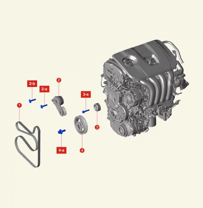
| 1. Drive Belt 2. Drive Belt Tensioner 2-a. 29.4 - 41 N·m 2-b. 39.2 - 49 N·m |
3. Idler 3-a. 39.3 - 49 N·m 4. Crankshaft Damper Pulley 4-a. 196.1 - 206 N·m |
Drive Belt Removal and Installation
Removal
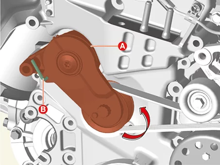
- Turn the auto tensioner pulley (A) counterclockwise using a wrench and insert the stopper pin (B) into the hole.
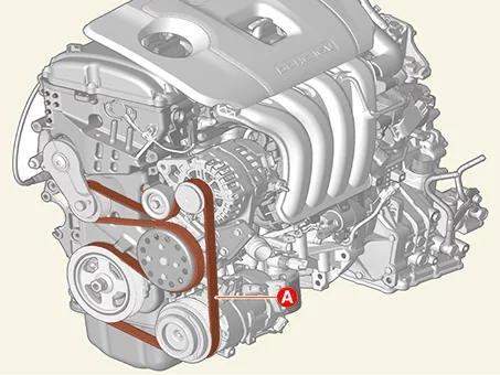
- Remove the drive belt (A).
Installation
- Install in reverse order of removal.
Drive Belt Inspection
Inspection
Visually check the belt for excessive wear, frayed cords etc. If any defect has been found, replace the drive belt.
Idler Removal and Installation
Removal
- Remove the drive belt. (Refer to Drive Belt System - "Drive Belt")
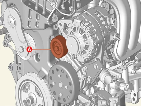
- Remove the idler (A) after removing the bolt.
Tightening torque : 39.2 - 49 N·m
Installation
- Install in reverse order of removal.
Install the Idler to the specified torque.
Drive Belt Tensioner Removal and Installation
Removal
- Remove the drive belt. (Refer to Drive Belt System - "Drive Belt")
- Remove the drive belt tensioner (A), after removing the bolt.
Tightening torque : Bolt (B) : 39.2 - 49 N·m (C) : 29.4 - 41 N·m
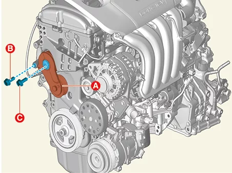
Installation
- Install in reverse order of removal.
Install the drive belt tensioner to the specified torque.
Crankshaft Damper Pulley Removal and Installation
Special Service Tool
| Ring gear stopper 09231 - 3D100 09231 - 2W100 |
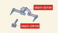 |
Used for removing / intalling crankshaft damper pulley |
| Ring gear stopper 09231-2B100 09231-3N100 |
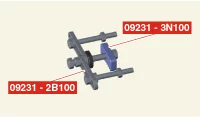 |
Used for removing / intalling crankshaft damper pulley |
Removal
- Remove the RH front wheel and tire. (Refer to Suspension System - "Wheel")
- Remove the engine room under cover. (Refer to Engine and Transaxle Assembly - "Engine Room Under Cover")
- Remove the drive belt. (Refer to Drive Belt System - "Drive Belt")
- Remove the crankshaft damper pulley (A), after removing the bolt.
Tightening torque : 196.1 - 206 N·m

To prevent deformation of the rubber part on the crankshaft damper pulley side, do not apply pressure to the pulley part or apply excessive external force.
Crankshaft damper pulley There are two ways to get on and fix the ring gear when mounted.- When removing / installing crankshaft damper pulley bolt, after removing the starter and using special tool (09231-2B100, 09231-3N100) to fix the ring gear. When removing the starter, (Refer to Engine Electrical System - "Starter")

- When removing / installing crankshaft damper pulley bolt, after removing the cover and using special tool (09231-3D100, 09231-2W100) to fix the ring gear.
- Remove the cover (A) after removing transaxle mounting bolt.
Tightening torque : 42.2 - 48 N·m
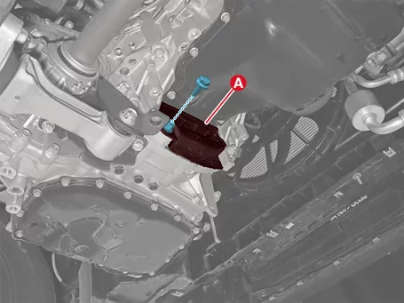
- Adjust the length with the nut (A) of the holder and install it by matching the teeth of the holder (B) and the ring gear (C).
- Adjust the angle of the arms (D) so that the two transaxle mounting bolts can be fastened tothe original mounted holes.
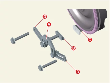
- Tighten the bolts and nuts of special tools (09231-3D100) completely.

- When removing / installing crankshaft damper pulley bolt, after removing the starter and using special tool (09231-2B100, 09231-3N100) to fix the ring gear. When removing the starter, (Refer to Engine Electrical System - "Starter")
Installation
- Install in reverse order of removal.
Install the crankshaft damper pulley to the specified torque.
Was this page helpful?