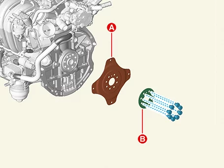
Remove the drive plate. (Refer to Cylinder Block - "Drive plate")
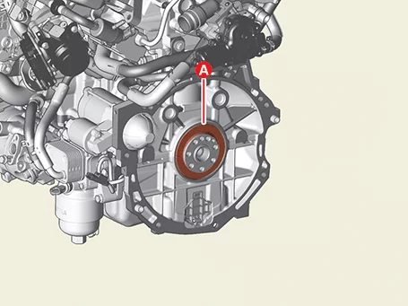
Remove the rear oil seal (A).
Install a new rear oil seal.
Apply engine oil on the edge of new oil seal.
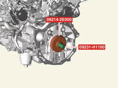
Using SST (09231 - H1100, 09214 - 2E000) and a hammer, tap in the oil seal until the SST face is aligned with the cylinder block assembly rear face.
Before assembling oil seal, the hardened sealant or hazardous material on the boundary area between cylinder block and ladder frame must be removed.
Install the oil seal by pressing it into the correct direction and be careful not to damage it.
Install in reverse order of removal.
Piston and Connecting Rod Disassembly
Disassembly
Use a fender cover to protect the painted surface.
Wait for the engine to cool to room temperature before disassembling to prevent damage to the cylinder head.
When handling a metal gasket, take care not to fold the gasket or damage the contact surface of the gasket.
Be careful not to damage the connector when disconnecting.
Mark all wiring and hoses to prevent incorrect connections.
Rotate the crankshaft to place the no.1 cylinder piston at the compress TDC.
Remove the engine and transaxle assembly from the vehicle. (Refer to Engine and Transaxle Assembly - "Engine and Transaxle Assembly")
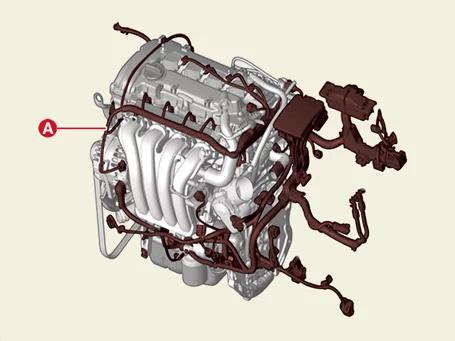
Disconnect the main wiring harness (A) from the engine room.
Remove the IVT. (Refer to Intelligent Variable Transmission (IVT) System - "Intelligent Variable Transmission (IVT)")
Install the engine assembly on the stand.
Remove the intake manifold. (Refer to Intake And Exhaust System - "Intake Manifold")
Remove the exhaust manifold. (Refer to Intake And Exhaust System - "Exhaust Manifold")
Remove the water temperature control assembly and heater pipe. (Refer to Cooling System - "Water Temperature Control Assembly")
Remove the compressor (Refer to Heating,Ventilation And Air Conditioning (Air Conditioner) – "Compressor")
Remove the alternator. (Refer to Engine Electrical System - "Alternator")
Remove the water pump. (Refer to Cooling System – "Water pump")
Remove the cylinder head cover. (Refer to Cylinder Head Assembly – "Cylinder Head Cover")
Remove the timing chain. (Refer to Timing System – "Timing Chain")
Remove the cylinder head assembly. (Refer to Cylinder Head Assembly - "Cylinder Head")
Remove the oil pan. (Refer to Lubrication - "Oil Pan")
Inspect the side clearance of connecting rod.
Remove the piston and connecting rod assembly from the cylinder block.
Remove the carbon deposits on the top of piston.
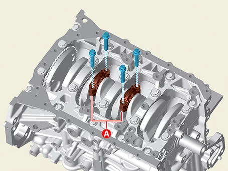
Remove the connecting rod bearing caps (A) after removing the bolts. Tightening torque : 1st step : 17.7 - 22 N·m 2nd step : 88 - 92°
Mark the connecting rod, and caps to be able to reassemble in the original position and direction.
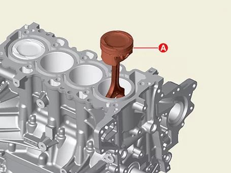
Push the piston and connecting rod assembly (A) with upper bearing through the top of the cylinder block.
Keep the connecting rod and cap with their bearings assembled together.
Arrange the piston and connecting rod assemblies in the correct order.
Mark the piston and connecting rod assemblies to be able to reassemble in the original position.
Measure the clearance between the piston and piston pin. Try to move the piston back and forth on the piston pin. If any movement is felt, replace the piston and piston pin as a set.
Remove piston rings.
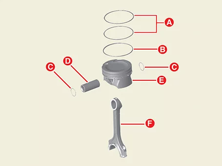
Remove the 2 piston rings (A).
Remove the oil ring (B).
Arrange the piston rings in the correct order.
Disassemble the connecting rod from the piston.
Remove the snap ring (C).
Remove the piston pin (D) from the piston.
Disassemble the piston (E) and connecting rod (F).
Piston and Connecting Rod Reassembly
Reassembly
Thoroughly clean all parts to be assembled.
Before installing the parts, apply fresh engine oil to all sliding and rotating surface.
Assemble the piston and the connecting rod.
Assemble the connecting rod (F) and piston (E).
Install the piston pin (D) on the piston.
Install the snap ring (C).
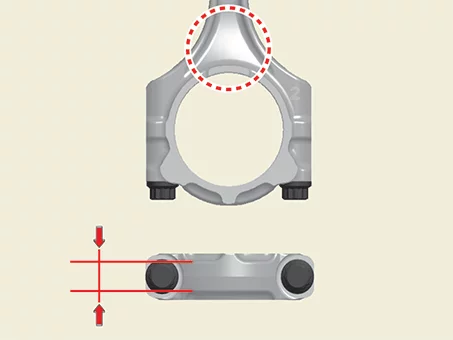
There are two types of connecting roads.
Install the same type of connecting rod assembly in all cylinders.
When replacing Type A, it can be substituted with a Type B connecting rod assembly.
When replacing Type B, do not substitute it with Type A. [Type A] [Type B]
Before assembling the piston pin, apply a sufficient amount of engine to the outer surface of piston, inner surface of piston hole and connecting small end bore.
When inserting, be careful not to damage or scratch the connecting rod small end hole, piston pin and piston pin hole.
Set the snap ring so that it contacts securely with the whole groove of the piston pin hole.
Install the piston ring.
Install the oil ring expander and the two side rails by hand.
Using a piston ring expander, install the 2 compression rings with the maker mark facing upward.
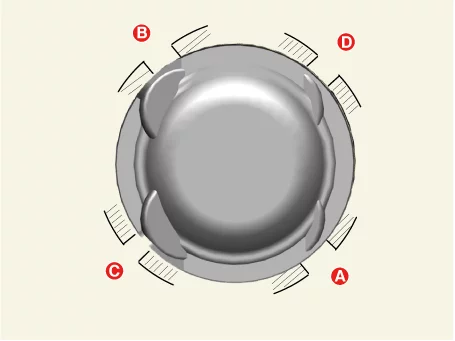
Make sure the end of each piston ring is seated as shown below. A : Lower side ring B : Upper side ring C : NO.2 ring D : NO.1 ring
Check to ensure that the oil ring can be turned smoothly.
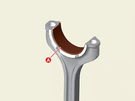
Install the connecting rod bearings.
Make sure that the grooves of the connecting rod and bearing cap are aligned with the protrusion of the bearing.
Install the bearing (A) on the connecting rod and the connecting rod bearing cap.
Be careful not to interchange the connecting rod and cap when installing.
Install the piston and connecting rod assembly.
Before installing the piston, apply a coat of engine oil to the ring grooves and cylinder bores.
Install the piston and connecting rod assembly with the front marks facing the front of the engine.
Install the ring compressor, check that the rings are securely in place, and then position the piston in the cylinder, and tap it in using the wooden handle of a hammer.
Insert the piston while pressing down the piston ring compressor to prevent the piston ring expansion before piston ring is inserted into the cylinder.
When the piston ring parts enter the cylinder, stop inserting and recheck the alignment of the journal and connecting rod.
Apply engine oil to the bolt threads. Install the rod caps (A) with bearings, and tighten the bolts. Tightening torque [Type A] Step 1 : 17.7 - 22 N·m Step 2 : 88 - 92° [Type B] Step 1 : 17.7 - 22 N·m Step 2 : 98 - 102°
Do not reuse connecting rod caps bolts.
Install the same type of connecting rod assembly in all cylinders.
When replacing Type A, it can be substituted with a Type B connecting rod assembly.
When replacing Type B, do not substitute it with Type A.
Check the connecting rod end play.
Assemble the other parts in the reverse order of disassembly.
Use a fender cover to protect the painted surface.
Wait for the engine to cool to room temperature before disassembling to prevent damage to the cylinder head.
When handling a metal gasket, take care not to fold the gasket or damage the contact surface of the gasket.
Be careful not to damage the connector when disconnecting.
Mark all wiring and hoses to prevent incorrect connections.
Rotate the crankshaft to place the no.1 cylinder piston at the compress TDC.
Remove the engine and transaxle assembly from the vehicle. (Refer to Engine and Transaxle Assembly - "Engine and Transaxle Assembly")
Remove the IVT from the engine and transaxle assembly. (Refer to Intelligent Variable Transmission (IVT) System - "Intelligent Variable Transmission (IVT)")
Install the engine assembly on the stand.
Remove the intake manifold. (Refer to Intake And Exhaust System - "Intake Manifold")
Remove the exhaust manifold. (Refer to Intake And Exhaust System - "Exhaust Manifold")
Remove the water temperature control assembly and heater pipe. (Refer to Cooling System - "Water Temperature Control Assembly")
Remove the alternator. (Refer to Engine Electrical System - "Alternator")
Remove the water pump. (Refer to Cooling System – "Water pump")
Remove the cylinder head cover. (Refer to Cylinder Head Assembly – "Cylinder Head Cover")
Remove the timing chain. (Refer to Timing System – "Timing Chain")
Remove the cylinder head assembly. (Refer to Cylinder Head Assembly - "Cylinder Head")
Remove the oil pan and oil screen. (Refer to Lubrication - "Oil Pan")
Remove the piston and connecting rod assembly. (Refer to Cylinder Block - "Piston and Connecting Rod")
Remove the lower crankcase (A).
Remove the lower crankcase mounting bolts (A).
Remove the main bearing cap bolts (A).
Remove the lower crankcase (A).
Check the crankshaft end play.
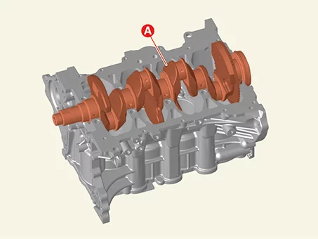
Remove the crankshaft (A) from the cylinder block. At this time, be careful not to damage the crankshaft journals.
Align the main bearing and thrust bearing in order.
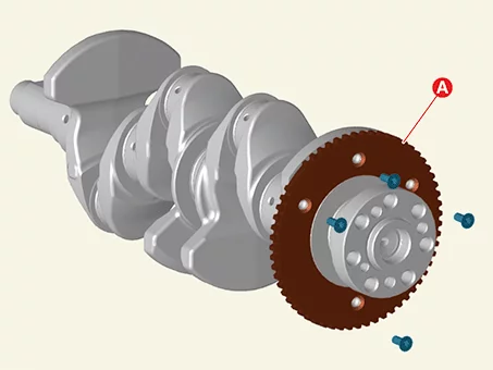
Remove the crankshaft position sensor wheel (A) after removing the bolt.
Tightening torque : 12.7 - 13,7 N·m
Remove the crankshaft main bearings.
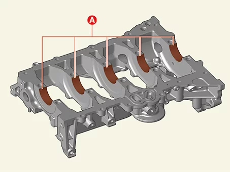
Remove the upper bearings (A).
Remove the lower bearings (A).
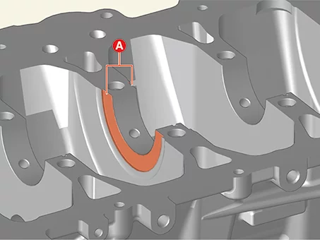
Remove the thrust bearing (A).
Remove the drive plate. (Refer to Cylinder Block - "Drive plate")
Remove the rear oil seal. (Refer to Cylinder Block - "Rear Oil Seal")
Crankshaft Reassembly
Reassembly
Thoroughly clean all parts to be assembled.
Before installing the parts, apply fresh engine oil to all sliding and rotating surface.
Install the main bearing.
Journal #1,3,5 upper bearing have an oil hole, and journal #2,4 upper bearing have an oil slot. but lower bearing do not.
Install the 5 upper bearings (A) by aligning the cylinder block groove and the bearing protrusion.
Install the 5 lower bearings by aligning the groove of the main bearing cap with the bearing protrusion.
Install the thrust bearings. Install the two thrust bearings (A) under the cylinder block No. 4 journal with the oil groove facing outward.
Install the crankshaft position sensor wheel (A).
Tightening torque : 12.7 - 13,7 N·m
Install the crankshaft (A) to the cylinder block.
Install the new O-ring (A) to the lower crankcase.
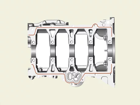
Apply liquid gasket to the lower crankcase mounting surface and then assemble within 5 minutes.
Be sure to remove the hardening sealant, foreign substance, oil, dust or moisture remaining on the liquid gasket sealing surface of the lower crankcase and cylinder block.
Apply a continuous bead of liquid gasket to the bottom surface of the lower crankcase, as shown in the illustration. Bead width : 3.5 - 4.5 mm (0.1378 - 0.1772 in.) Sealant : Threebond 1217H or equivalent
Assemble the lower crankcase within 5 minutes after applying sealant.
The engine running or pressure test should not be performed within 30 minutes after assembling the lower crankcase.
Excess sealant on application surface of sealant of following process should be removed before hardening.
If the sealant is applied to the top surface of the lower crankcase, it should be the same position as the cylinder block.
To prevent leakage of oil, apply sealant gasket on the inner threads of the bolt holes.
Install the lower crankcase to the cylinder block.
Install the lower crankcase (A).
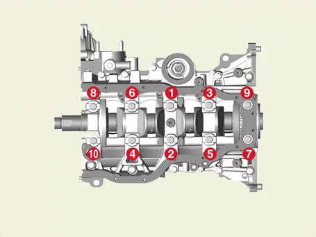
Install the main bearing cap bolts (A). Divide the 10 bolts 2steps in the order shown in the figure below and tighten them evenly. Tightening torque 1st step : 27.5 - 31 N·m 2nd step : 120 - 125°
Do not reuse the main bearing cap bolts.
Intall the lower crankcase mounting bolts (A). Tighten the lower crankcase mounting bolts several times according to the tightening below sequence.
Tightening torque : 18.6 - 24 N·m
Check if the crankshaft rotates smoothly.
Check the crankshaft end play.
Assemble the other parts in the reverse order of disassembly.
When replacing the crankshaft, select and install the appropriate connecting rod bearing according to the pin journal mark on the crankshaft.
Connecting rod bearing selection. (Refer to Cylinder Block - "Piston and Connecting Rod")
Crankshaft Inspection
Inspection
Check the crankshaft bearing oil clearance.
Remove bearing and cap to measure the main journal bearing oil clearance.
Clean each main journal and bearing using a cloth, etc.
Place one strip of plastigage across each main journal.
Tighten the main bearing cap bolts several times according to the tightening below sequence. Tightening torque : 1st step : 27.5 - 31 N·m 2nd step : 120 - 125°
Do not reuse the main bearing cap bolts.
Tighten the lower crankcase mounting bolts several times according to the tightening below sequence.
Remove the lower crankcase and lower bearings and measure the width of the plastigage at its widest point.
If the plastigage measures too wide or too narrow, remove the upper and lower bearing and then install a new bearings with the same color mark. Recheck the oil clearance.
Do not adjust the clearance by machining the bearing or cap.
If the remeasured value is still out of the specified value, install the next larger or smaller bearing and then remeasure the oil clearance. (refer to the crankshaft bearing selection table)
If the proper clearance cannot be obtained by using the appropriate larger or smaller bearings, replace the crankshaft and repeat the check procedure.
If the proper clearance cannot be obtained by using the appropriate larger or smaller bearings, replace the crankshaft and repeat the check procedure.
If the marks are indecipherable because of an accumulation of dirt and dust, do not scrub them with a wire brush or scraper. Clean them only with solvent or detergent.
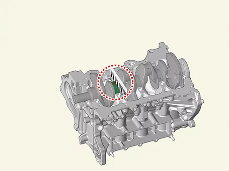
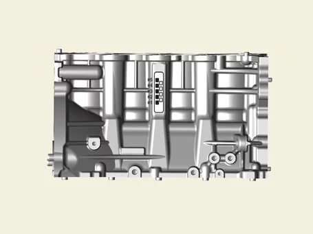
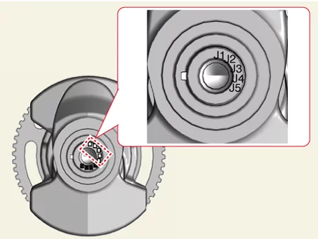
Classification Mark Position For Crankshaft Bore Inner Diameter The each size mark of the 5 main journal bores is engraved on the side of cylinder block. Use the journal bore markings engraved on the block and the journal bore markings on the crankshaft for correct bearing selection. Cylinder Block Journal Bore Classification Table
Class
Mark
a
A
59.000 - 59.006 mm (2.32283 - 2.32307 in.)
b
B
59.006 - 59.012 mm (2.32307 - 2.32330 in.)
c
C
59.012 - 59.018 mm (2.32330 - 2.32354 in.)
sification Mark Position For outer Diameter Of Crankshaft Pin Crankshaft Main Journal Classification Table
Class
Mark
I
1
54.954 - 54.960 mm (2.16354 - 2.16378 in.)
II
2
54.948 - 54.954 mm (2.16330 - 2.16354 in.)
III
3
54.942 - 54.948 mm (2.16307 - 2.16330 in.)
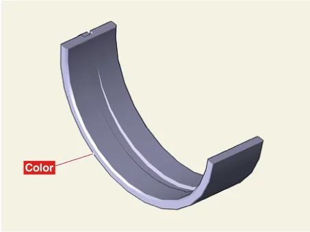
Classification Mark Position Of Crankshaft Bearing Crankshaft Bearing Specifications
Class
Mark
Connecting rod bearing thickness
A
Light Blue
2.021 ~ 2.024 mm (0.07957 - 0.07968 in.)
B
Black
2.018 ~ 2.021 mm (0.07945 - 0.07957 in.)
C
White
2.015 ~ 2.018 mm (0.07933 - 0.07945 in.)
D
Light Green
2.012 ~ 2.015 mm (0.07921 - 0.7933 in.)
E
Pink
2.009 ~ 2.012 mm (0.07909-0.07921 in.)
Select the proper crankshaft main bearing using the below bearing selection table. Crankshaft Main Bearing Selection Table
Crankshaft Bore Identification Mark
a
b
c
Crankshaft Identification Mark
I (1)
E (Pink)
D (Light Green)
C (White)
II (2)
D (Light Green)
C (White)
B (Black)
III (3)
C (White)
B (Black)
A (Light Blue)
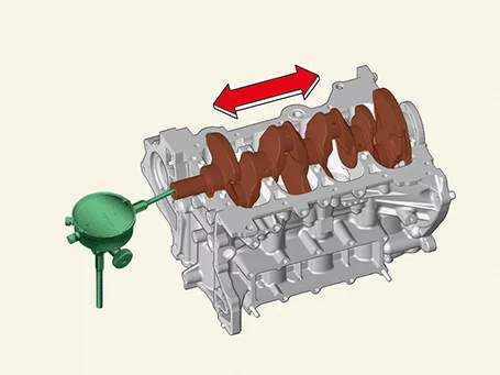
Measure the crankshaft end play. Check the axial clearance by moving the crankshaft back and forth using a dial gauge. If end play exceeds limit value, replace the thrust bearing.
Standard : 0.07 - 0.25 mm (0.0028 - 0.0098 in.)
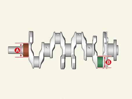
Inspect main journals and crank pins. Using a micrometer, measure the diameter of each main journal (A) and crank pin (B). Main journal diameter : 54.942 - 54.960 mm (2.16307 - 2.16378 in.) Crank pin diameter : 44.954 - 44.972 mm (1.76984 - 1.77055 in.)
Cylinder Block Disassembly
Disassembly
Use a fender cover to protect the painted surface.
Wait for the engine to cool to room temperature before disassembling to prevent damage to the cylinder head.
When handling a metal gasket, take care not to fold the gasket or damage the contact surface of the gasket.
Be careful not to damage the connector when disconnecting.
Mark all wiring and hoses to prevent incorrect connections.
Rotate the crankshaft to place the no.1 cylinder piston at the compress TDC.
Remove the engine and transaxle assembly from the vehicle. (Refer to Engine and Transaxle Assembly - "Engine and Transaxle Assembly")
Remove the IVT from the engine and transaxle assembly. (Refer to Intelligent Variable Transmission (IVT) System - "Intelligent Variable Transmission (IVT)")
Install the engine assembly on the stand.
Remove the intake manifold. (Refer to Intake And Exhaust System - "Intake Manifold")
Remove the exhaust manifold. (Refer to Intake And Exhaust System - "Exhaust Manifold")
Remove the water temperature control assembly and heater pipe. (Refer to Cooling System - "Water Temperature Control Assembly")
Remove the alternator. (Refer to Engine Electrical System - "Alternator")
Remove the water pump. (Refer to Cooling System – "Water pump")
Remove the cylinder head cover. (Refer to Cylinder Head Assembly – "Cylinder Head Cover")
Remove the timing chain. (Refer to Timing System – "Timing Chain")
Remove the cylinder head assembly. (Refer to Cylinder Head Assembly - "Cylinder Head")
Remove the oil pan and oil screen. (Refer to Lubrication - "Oil Pan")
Remove the piston and connecting rod assembly. (Refer to Cylinder Block - "Piston and Connecting Rod")
Remove the Crankshaft Position Sensor (CKPS). (Refer to Engine Control / Fuel System - "Crankshaft Position Sensor (CKPS)")
Remove the crankshaft. (Refer to Cylinder Block - "Crankshaft")
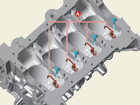
Remove the piston cooling oil jet (A), after removing the bolts.
Tightening torque : 8.8 - 10,8 N·m
Cylinder Block Reassembly
Reassembly
Thoroughly clean all parts to be assembled.
Before installing the parts, apply fresh engine oil to all sliding and rotating surface.
Do not reuse gaskets, o-rings and oil rings.
Install the piston cooling oil jet (A).
Tightening torque : 8.8 - 10,8 N·m
Assemble the other parts in the reverse order of disassembly.
Install the cylinder block to the specified torque.
When replacing the cylinder block, select and install the appropriate crankshaft main bearings and pistons according to the crankshaft journal bore mark and the cylinder bore size mark on the cylinder block.
Crankshaft main bearing selection. (Refer to Cylinder Block - "Crankshaft")
piston selection. (Refer to Cylinder Block - "Piston and Connecting Rod")
Cylinder Block Inspection
Inspection
Remove the gasket debris on the top of cylinder block using a scraper.
Using a soft brush and solvent, thoroughly clean the cylinder block.
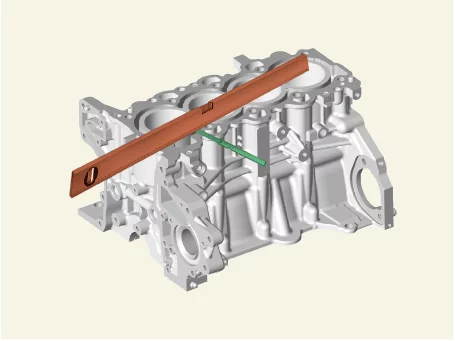
Measure the flatness of the top surface of cylinder block. Measure the flatness of the surface in contact with the cylinder head gasket using the precise square ruler and feeler gauge. Flatness of cylinder block gasket face Standard : Less than 0.050 mm (0.0020 in.) for total area Less than 0.020 mm (0.0008 in.) for a section of 100.000 mm (3.9370 in.) X 100.000 mm (3.9370 in.)
Visually inspect the inside of cylinder bore for scratches, etc., and replace the cylinder block if noticeable scratches are found.
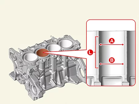
Using a cylinder bore gauge, measure the inner diameter points A and B of the cylinder bore in the axial and vertical directions.