Engine Mechanical System
Timing System
In this manual: Engine Mechanical System
40steps
~245min
5/5difficulty
1special tools
Done 0 of 40
Contents:
Components and Components Location
Component
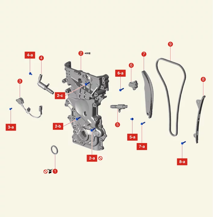
| 1. Front oil seal 2. Timing Chain Cover 2-a. 16.7 - 24 N·m 2-b. 9.8 - 11,8 N·m 2-c. M8 bolt 18.6 - 24 N·m 2-c. M10 bolt 39.2 - 49 N·m 3. Intake Middle Lock Control Solenoid 3-a. 8.8 - 9,8 N·m |
4. CVVT CVVT Oil Control Valve (OCV) - Exhaust 4-a. 9.8 - 11,8 N·m 5. CVVT CVVT Oil Control Valve (OCV) - Intake 5-a. 9.8 - 11,8 N·m 6. Timing chain tensioner 6-a. 9.8 - 11,8 N·m 7. Timing chain tensioner arm 7-a. 18.6 - 23 N·m 8. Timing Chain Guide 8-a. 18.6 - 23 N·m 9. Timing Chain |
Front Oil Seal Replacement
Special Service Tool
| Tool Name / Number | Illustration | Description |
| front oil seal installer 09231 - 2E000 |
 |
Used for installing crankshaft front oil seal |
Replacement
- Remove the crankshaft damper pulley. (Refer to Drive Belt System - "Crankshaft Damper Pulley")
- Remove the front oil seal (A).
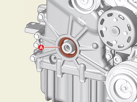
- Apply engine oil to the edge of the new oil seal.
Remove any debris from the oil seal lip.
- Use SST (09231-2E000) and a rubber mallet to lightly tap and install the new front oil seal.

Do not reuse front oil seal.
Timing Chain Cover Removal
Removal
|
|

- Disconnect the battery negative ( - ) terminal.
- Remove the engine cover. (Refer to Engine and Transaxle Assembly - "Engine Cover")
- Remove the intake middle lock control solenoid. (Refer to Engine Control / Fuel System - "Intake Middle Lock Control Solenoid")
- Remove the RH front wheel and tire. (Refer to Suspension System - "Wheel")
- Remove the engine room under cover. (Refer to Engine and Transaxle Assembly - "Engine Room Under Cover")
- Remove the cylinder head cover. (Refer to Cylinder Head Assembly - "Cylinder Head Cover")
- Remove the air conditioning compressor. (Refer to Heating, Ventilation and Air Conditioning - "Compressor")
- Remove the oil pan. (Refer to Lubrication - "Oil Pan")
- Remove the engine mounting support bracket. (Refer to Engine And Transaxle Assembly - "Engine Mounting")
- Remove the crankshaft damper pulley. (Refer to Drive Belt System - "Crankshaft Damper Pulley")
- Remove the idler. (Refer to Drive Belt System - "Idler")
- Remove the alternator. (Refer to Engine Electrical System - "Alternator")
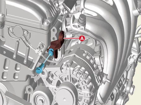
- Remove the front engine hanger (A), after removing the bolt.
Tightening torque : 34.3 - 39 N·m
- Remove the drive belt tensioner. (Refer to Drive Belt System - "Drive Belt Tensioner")
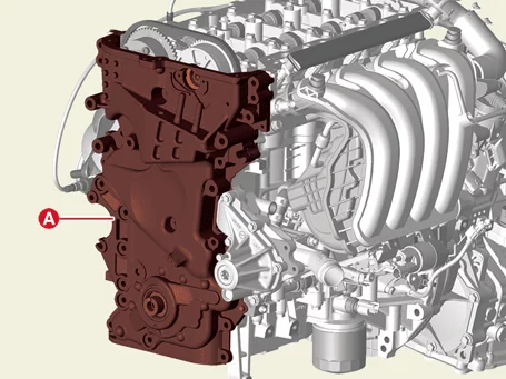
- Remove the timing chain cover (A) after removing the bolts.
Tightening torque (A, B) : 18.6 - 24 N·m (C) : 19.6 - 24 N·m (D, E) : 39.2 - 49 N·m (F) : 9.8 - 11,8 N·m
- When removing the timing chain cover, be careful not to damage the contact surfaces of the cylinder block, cylinder head and lower crankcase.
- Do not disassemble the oil pump from timing chain cover because it is supplied as timing chain cover & oil pump assembly.

Timing Chain Cover Installation
Installation
- Install the timing chain cover.
- The sealant locations on the chain cover and the counter parts (timing chain cover, cam carrier, cylinder head, cylinder block, and lower crankcase) must be free of harmful foreign materials, oil, dust and moisture. Spraying cleaner on the surface and wiping with a clean duster.
- Before assembling the timing chain cover, liquid sealant should be applied on the gap between cam carrier, cylinder head and cylinder block.
Bead width : 3.500 - 4.500 mm (0.14 - 0.18 in.) Sealant : Threebond 1217H or equivalent
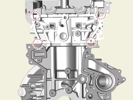
- Install within 5 minutes after applying sealant to the mounting surface of the timing chain cover.
Bead width Whole section : 2.5 - 3.5 mm (0.10 - 0.14 in.) Section A : 4.5 - 5.5 mm (0.18 - 0.22 in.) Section B : 8.0 - 9.0 mm (0.32 - 0.35 in.) Sealant : Threebond 1217H or equivalent
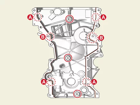
- Install the timing chain cover (A) using the dowel pin of the cylinder block and the hole of the timing chain cover as a reference.
Tightening torque (A, B) : 18.6 - 24 N·m (C) : 19.6 - 24 N·m (D, E) : 39.2 - 49 N·m (F) : 9.8 - 11,8 N·m
Do not start the engine or apply pressure to the cover 30 minutes after assembling the timing chain cover.
- front oil seal exchange if necessary. (Refer to Timing System – "Front Oil Seal")
- Install in reverse order of removal.
Install the timing chain cover to the specified torque.
Timing Chain Removal
Removal
|
- Remove the cylinder head cover. (Refer to Cylinder Head Assembly - "Cylinder Head Cover")
- Set No.1 cylinder to TDC (Top dead center) on compression stroke.
- Turn the crankshaft damper pulley clockwise to bring the piston of cylinder 1 to compression top dead center so that the timing mark on the timing chain cover matches the groove on the damper pulley.
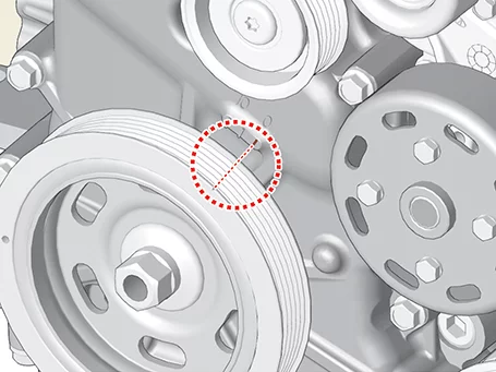
- Check that the timing marks on the intake camshaft sprocket and exhaust camshaft sprocket are aligned.
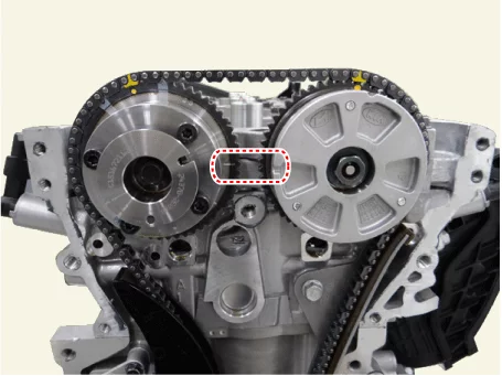
If the timing marks do not match, rotate the crankshaft one more revolution. (Do not reverse the engine at this time.)
- Turn the crankshaft damper pulley clockwise to bring the piston of cylinder 1 to compression top dead center so that the timing mark on the timing chain cover matches the groove on the damper pulley.
- Remove the timing chain cover. (Refer to Timing System - "Timing Chain Cover")
- Compress the piston and then insert a stopper pin (A) into the hole to fix the piston and then remove the tensioner (B).
Tightening torque : 9.8 - 11,8 N·m
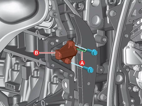
Do not reuse the timing chain tensioner. - Remove the timing chain tensioner arm (A) after removing the bolt.
Tightening torque : 18.6 - 23 N·m
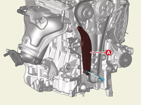
- Remove the timing chain (A).
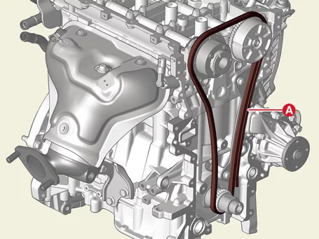
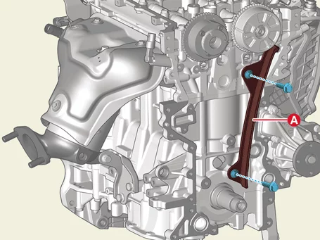
- Remove the timing chain guide (A) after removing the bolts.
Tightening torque : 18.6 - 23 N·m
Timing Chain Installation
Installation
|
- The TDC marks of the intake and exhaust CVVT sprockets are slightly turned from the TDC position as shown when the timing chain is removed.
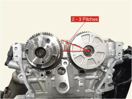
- Turn the crankshaft clockwise (about 2-3 pitches) from the TDC position (the dowel pin (A) of crankshaft is about 3° with the engine vertical line) as rotation of the intake CVVT sprocket from the TDC position.
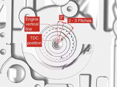
- Install the timing chain guide, and then tighten the bolt.
Tightening torque : 18.6 - 23 N·m
- Install the timing chain. Crankshaft sprocket → timing chain guide → Intake CVVT sprocket → exhaust CVVT sprocket
- Install the timing chain with no slack between the crankshaft sprocket and the intake CVVT sprocket.

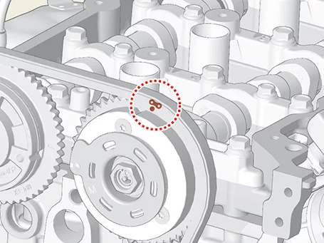
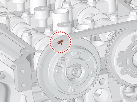
- Install the timing chain on the exhaust CVVT sprocket with no slack while turning the CVVT assembly clockwise by using rachet (A).
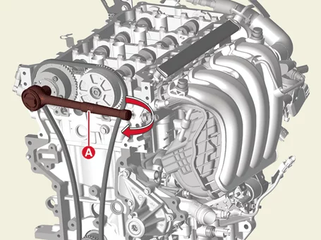
- The timing mark of the exhaust CVVT sprocket should be matched with timing mark (color link) of timing chain when installing the timing chain.
- Press down the timing chain links on the exhaust CVVT sprocket to prevent the sprocket from spinning.
- Install the timing chain with no slack between the crankshaft sprocket and the intake CVVT sprocket.
- Install the timing chain tensioner arm, and then tighten the bolt.
Tightening torque : 18.6 - 23 N·m
- Install the timing chain tensioner (B), tighten the bolts, and remove the fixing pin (A).
Tightening torque : 9.8 - 11,8 N·m
Do not reuse the timing chain tensioner. - Turn the crankshaft clockwise 2 turns and check that the TDC marks on the front of the intake and exhaust CVVT sprockets are facing each other.
If the timing marks do not match, rotate the crankshaft one more revolution. (Do not reverse the engine at this time.) - Assemble the other parts in the reverse order of disassembly.
Install the timing chain to the specified torque.
Timing Chain Inspection
Inspection
Sprockets, Chain Tensioner, Chain Tensioner Arm, Chain Guide- Check the CVVT sprocket, crankshaft sprocket teeth for abnormal wear, cracks or damage. Replace if necessary.
- Check a contact surface of the chain tensioner arm and guide for abnormal wear, cracks or damage,Replace if necessary.
- Check that the chain tensioner piston slides smoothly and inspect whether the ratchet operates normally. Replace if necessary.
Was this page helpful?