Engine Mechanical System
Engine Cover Removal and Installation
In this manual: Engine Mechanical System
50steps
~300min
4/5difficulty
Done 0 of 50
Contents:
Engine Cover Removal and Installation
Removal
- Remove the engine cover (A).
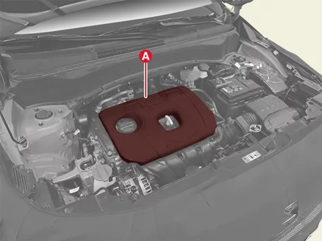

- Remove the engine cover at room temperature.
- Do not remove the two mounting points of the engine cover at the same time.
Installation
- Install in reverse order of removal.
Engine Room Under Cover Removal and Installation
Removal
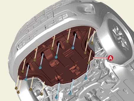
- Remove the engine room under cover (A) after removing the fastener and bolts.
Tightening torque : 7.8 - 11,8 N·m
Installation
- Install in reverse order of removal.
|
Engine Mounting Components and Components Location
Component

| 1. Engine Mounting Bracket 1-a. 49.0 - 64 N·m 2. Engine Mounting Support Bracket. 2-a. 78.5 - 98 N·m 2-b. 78.5 - 98 N·m |
3. Roll Rod Bracket 3-a. 49.0 - 64 N·m 3-b. 107.9 - 128 N·m 4. IVT Mounting Bracket 4-a. 49.0 - 64 N·m 4-b. 98.1 - 118 N·m |
Engine Mounting Removal and Installation
Removal
Engine Mounting Bracket- Remove the engine room under cover. (Refer to Engine and Transaxle Assembly - "Engine Room Under Cover")
- Install the jack to the edge of oil pan to support the engine.
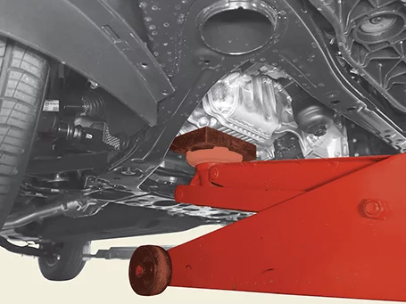
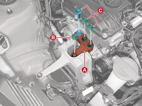
Put a rubber pad between the lower oil pan and the jack to prevent damage to the oil pan. - Remove the engine mounting support bracket (A), after removing the bolt and nuts.
Tightening torque (B) : 78.5 - 98 N·m (C) : 78.5 - 98 N·m
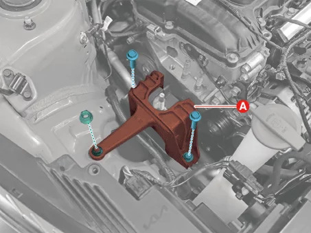
- Remove the engine mounting bracket (A), after removing the bolt and nut.
Tightening torque : 49.0 - 64 N·m
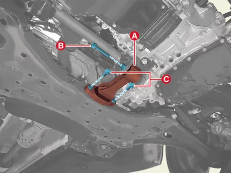
- Remove the roll rod bracket (A) after removing the bolts (B, C).
Tightening torque (B) : 107.9 - 128 N·m (C) : 49.0 - 64 N·m
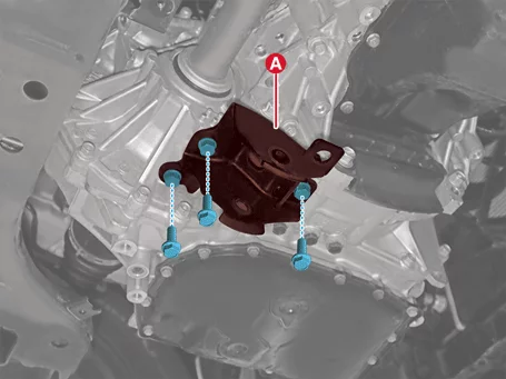
- Remove the roll rod mounting support bracket (A), after removing the bolts.
Tightening torque : 49.0 - 69 N·m
- Disconnect the battery negative ( - ) terminal.
- Remove the air duct and air cleaner assembly. (Refer to Intake and Exhaust System - "Air Cleaner")
- Remove the battery. (Refer to Engine Electrical System - "Battery")
- Remove the Engine Control Module (ECM). (Engine Control / Fuel System - "Engine Control Module (ECM)")
- Remove the battery tray. (Refer to Engine Electrical System - "Battery")
- Remove the LH front wheel guard. (Refer to Body - "Front Wheel Guard")
- Remove the engine room under cover. (Refer to Engine and Transaxle Assembly – "Engine Room Under Cover")
- Support the IVT securely using a jack.
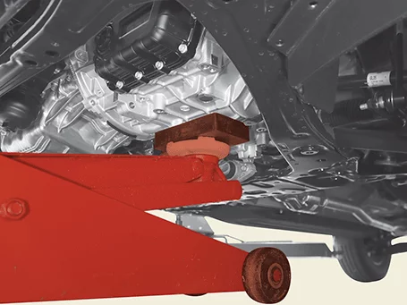
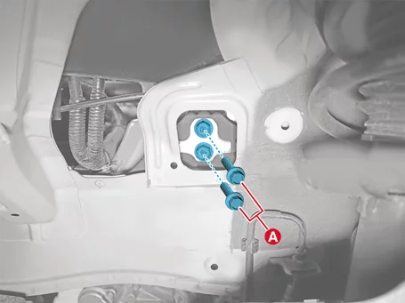
Put a rubber pad between the IVT and the jack to prevent damage to the IVT. - Remove the IVT mounting bracket bolts (A).
Tightening torque : 98.1 - 118 N·m
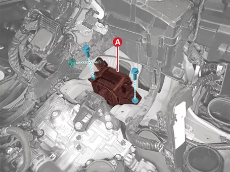
- Remove the IVT mounting bracket (A) after removing bolts and nut.
Tightening torque : 49.0 - 64 N·m
Installation
Engine Mounting Bracket
- Install in reverse order of removal.
Install the engine mounting to the specified torque.
Roll Rod Bracket
- Install in reverse order of removal.
Install the roll rod bracket to the specified torque.
IVT Mounting Bracket
- Install in reverse order of removal.
Install the IVT mounting bracket to the specified torque.
Engine and Transaxle Assembly Removal
Removal
|
|

- Release the residual pressure in fuel line. (Refer to Fuel Delivery System - "Release Residual Pressure in Fuel Line")
- Disconnect the battery negative ( - ) terminal.
- Remove the engine cover. (Refer to Engine And Transaxle Assembly - "Engine Cover")
- Remove the air duct and air cleaner assembly. (Refer to Intake and Exhaust System - "Air Cleaner")
- Remove the battery. (Refer to Engine Electrical System - "Battery")
- Remove the Engine Control Module (ECM). (Refer to Engine Control / Fuel System - "Engine Control Module (ECM)")
- Remove the battery tray. (Refer to Engine Electrical System - "Battery")
- Remove the engine room under cover. (Refer to Engine and Transaxle Assembly – "Engine Room Under Cover")
- Drain the coolant. (Refer to Cooling System - "Coolant")
- Disconnect the A/C compressor high pressure pipe and low pressure pipe. (Refer to Heating, Ventilation and Air Conditioning - "Compressor")
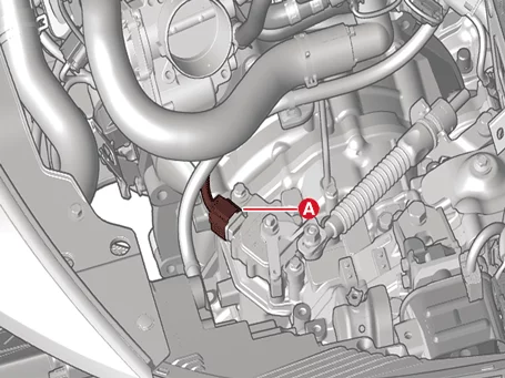
- Disconnect the position switch connector (A).
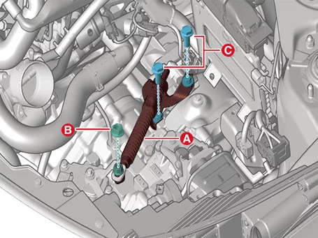
- Remove the shift cable (A) after removing the bolts (C) and nut (B).
Tightening torque (B) : 9.8 - 13,7 N·m (C) : 14.7 - 22 N·m
- Disconnect the main wiring harness from the engine room.
- Disconnect the fuse box main wiring connector (A).
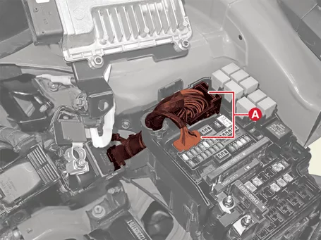
- Disconnect the fuse box wiring cable (A), after removing the nut.
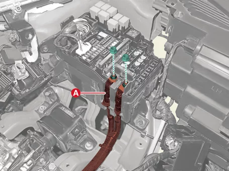
- Disconnect the main wiring harness (A) from the engine room.
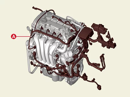
- Disconnect the fuse box main wiring connector (A).
- Separate the radiator upper hose (A) after releasing the clamp.

- Separate the radiator lower hose (A) after releasing the clamp.
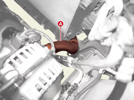
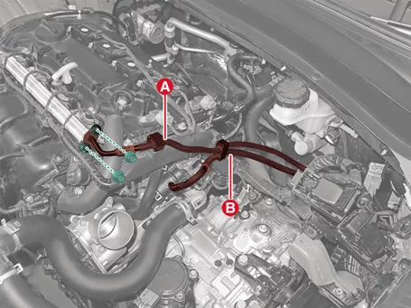
- Disconnect the fuel hose (A) and Purge Control Solenoid Valve (PCSV) hose (B) after removing nuts.
Tightening torque : 8.8 - 11,8 N·m
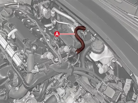
- Release the clamp, and then disconnect the brake booster vacuum hose (A).
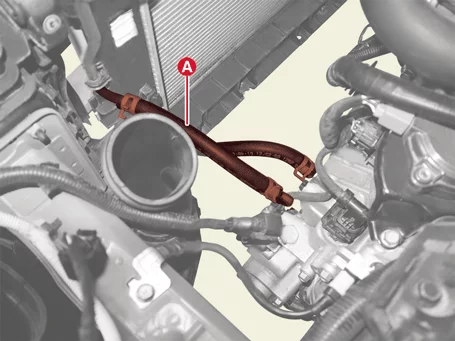
- Separate the IVTF cooler hoses (A) after releasing the clamp.
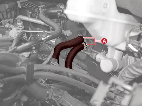
- Release the clamp, and then disconnect the heater hose (A).
- Remove the front muffler. (Refer to Intake And Exhaust System – "Muffler")
- Remove the roll rod bracket (A) after removing the bolts (B, C).
Tightening torque (B) : 107.9 - 128 N·m (C) 49.0 - 64 N·m
- Remove the roll rod mounting support bracket (A), after removing the bolts.
Tightening torque : 49.0 - 69 N·m
- Remove the front sub-frame. (Refer to Suspension System – “Front Sub Frame”)
If you loosen the front sub frame fixing bolts, the engine and transaxle assembly may fall, so support the jack safely. - Remove the propeller shaft.(AWD type) (Refer to All Wheel Drive (AWD) System - "Propeller Shaft")
- Remove the front driveshaft. (Refer to Driveshaft and Axle - "Front Driveshaft")
- Support the engine and transaxle assembly securely with a follower jack.
- Separate the engine ground cable (A) after removing the bolt.
Tightening torque : 10.8 - 13,7 N·m
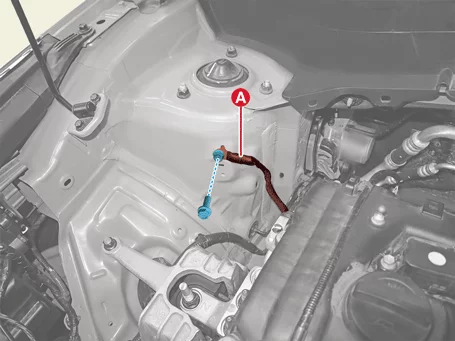
- Disconnect the transaxle grounding cable (A) after removing the bolt.
Tightening torque : 26.5 - 32 N·m
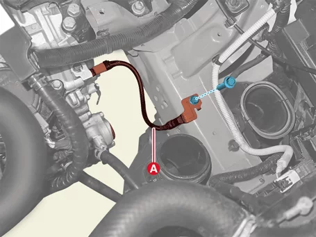
- Remove the engine mounting support bracket (A), after removing the bolt and nuts.
Tightening torque : (B) : 78.5 - 98 N·m (C) : 78.5 - 98 N·m
- Remove the LH front wheel guard. (Refer to Body - "Front Wheel Guard")
- Remove the IVT mounting bracket bolts (A).
Tightening torque : 98.1 - 118 N·m
- Remove the engine and transaxle assembly (A) by lifting vehicle.
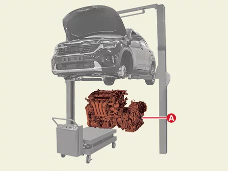
- Before removing the engine and transaxle assembly, make sure hoses and wire connectors are disconnected.
- When removing the engine and transaxle assembly, be careful not to damage any surrounding parts or body components.
Engine and Transaxle Assembly Installation
Installation
- Install in reverse order of removal.
Install the Engine And Transaxle Assembly to the specified torque. - Fill the coolant. (Refer to Cooling System - "Coolant")
- Check for fuel leaks.
- After assembling the fuel line, turn on the key (at this time, do not start the engine) and drive the fuel pump for about 2 seconds to create pressure in the fuel line.
- After repeating the above operation 2-3 times, check that there is no fuel leak in the fuel line.
- After cleaning the battery terminals and cable terminals with sandpaper, assemble them
Was this page helpful?