Front View Camera Module
Circuit Diagrams
Wiring Diagram

Repair Procedures
Inspection
In the electrical body system, malfunctions can be quickly diagnosed using the Kia Diagnostic System (KDS).
The Diagnostic System (KDS) provides the following information.
Self-diagnosis: check for malfunction and diagnostic trouble code (DTC).
Current Data: Check the system input/output status.
Operation check: Check the operating status of the system.
Special Function: Control of other functions, including parameter setting and zero point adjustment.
Removal
Read the specification information for the front view camera installed in the vehicle before replacing it with a new front view camera.
Connect the VCI-II wireless adapter to the Data Link Connector (DLC) located under the instrument panel on the driver's side, then turn on KDS.
Select "Software Management" and "Vehicle Model".
Select "Front View Camera" and "System Identification."

Disconnect the negative (-) battery terminal.
Remove the inside rearview mirror cover (A) and the unit cover (B).


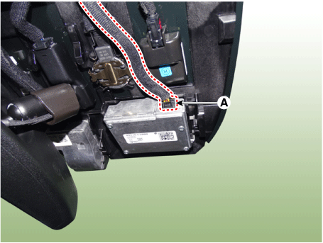
Disconnect the front view camera connector (A).
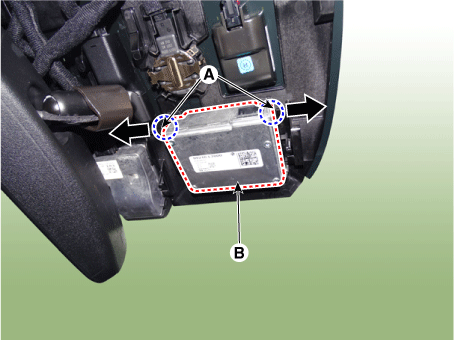
Release the fixing points (A) of the bracket, then remove the front view camera (B).
Installation
Install in the reverse order of removal.
When replacing the front view camera with a new one, perform "Variant Coding" using KDS.

Perform calibration of the front view camera unit.
(Refer to Front View Camera Unit - "Adjustment")
Adjustment
Service Target Point Automatic Calibration (SPTAC) Procedure
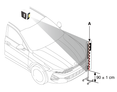
Install SST (09964-C1200) at the center of the roof above the front windshield.

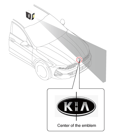
Project the laser starting from the center of the roof and passing through the center of the emblem.
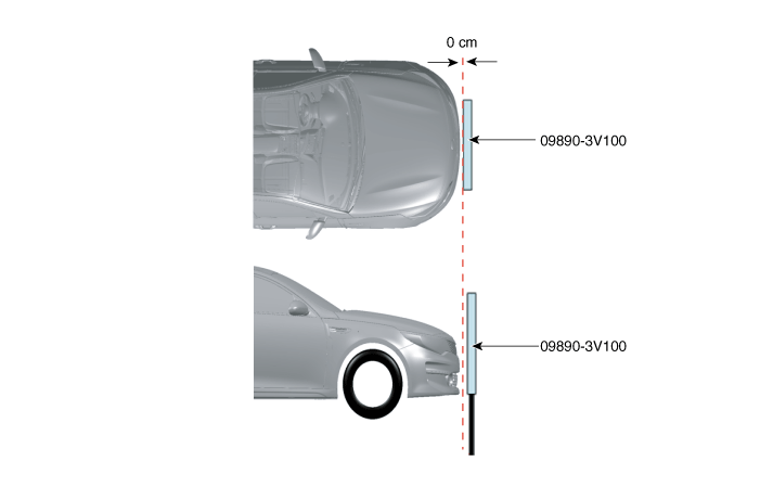
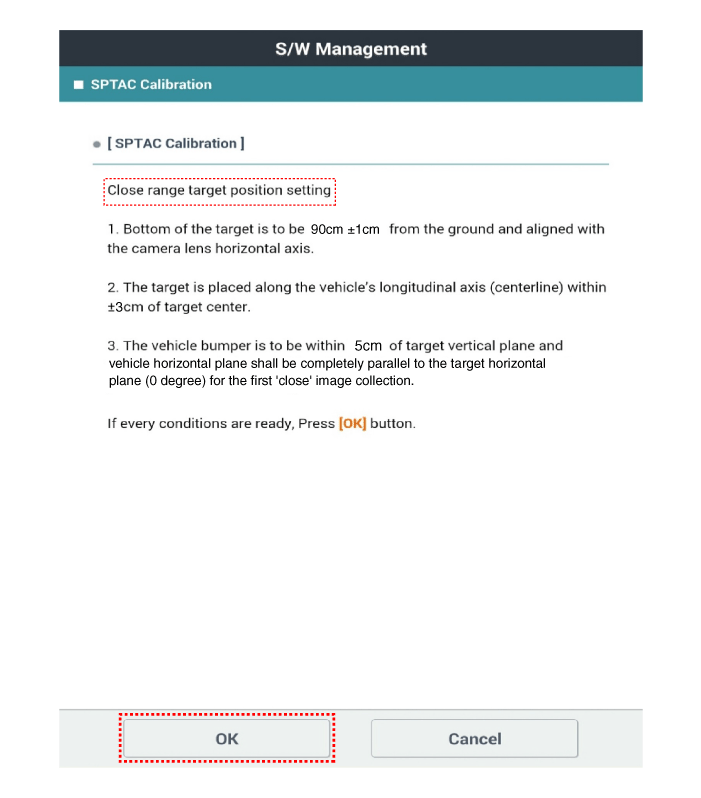
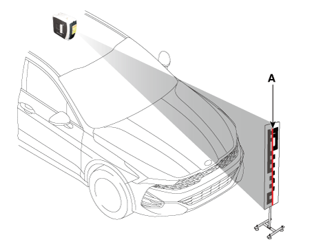
Place the calibration target (09890-3V100) so that it is 0 cm from the front of the bumper. [Max. tolerance: 5 cm (1.97 in.)]
Set the height of the calibration target to 90 ± 1 cm (35.43 ± 0.39 in.) from the ground, and align the center of the calibration target with the center line (A) of the laser beam.
The target is positioned along the longitudinal axis (centerline) of the vehicle within ± 3 cm (± 1.18 in.) from the center of the target.
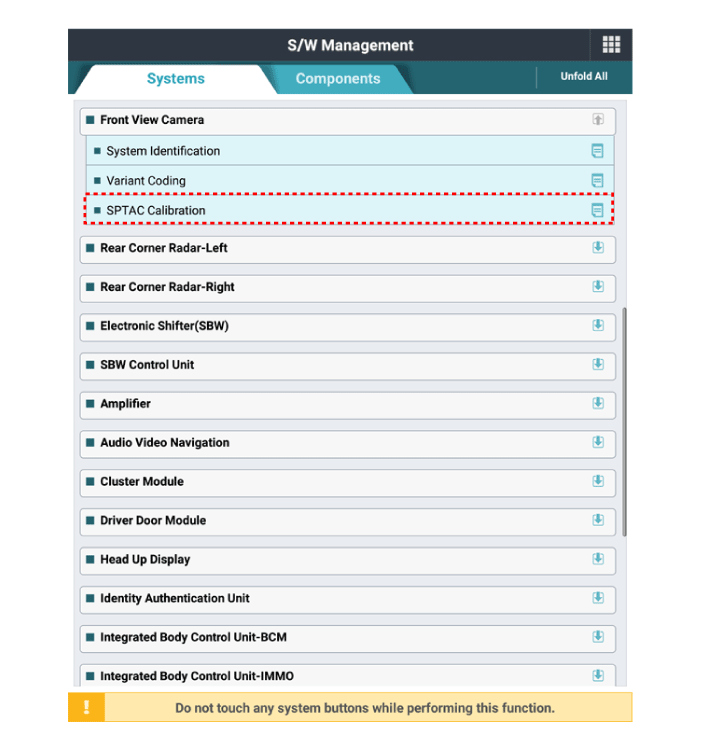
Perform "SPTAC Calibration" using KDS.
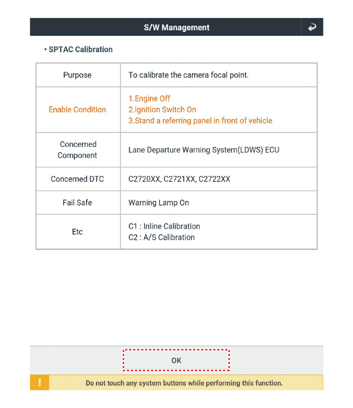
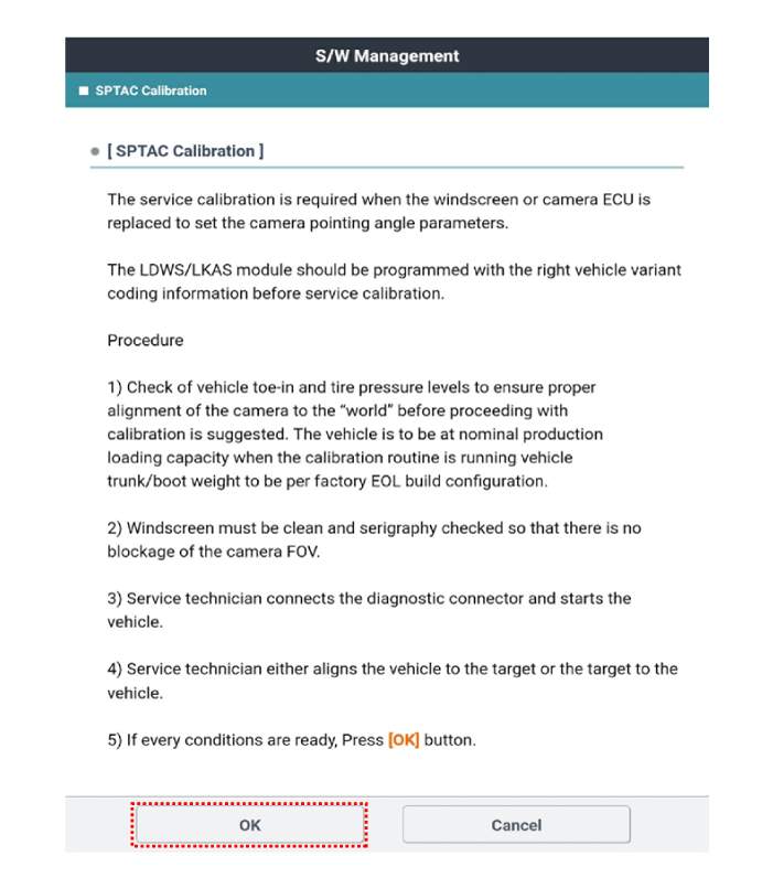
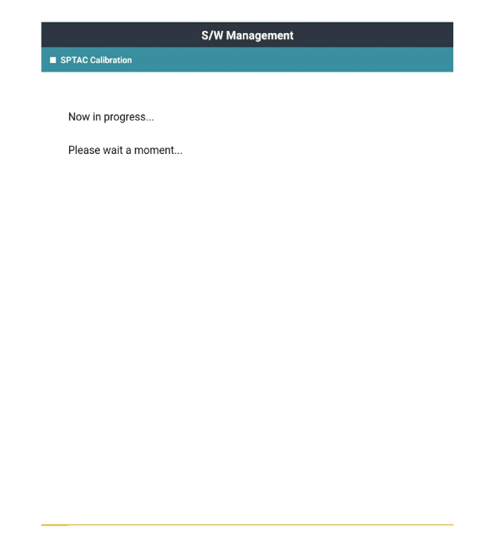
Perform short-range calibration by selecting the "OK" message on KDS after checking the position of the calibration target.
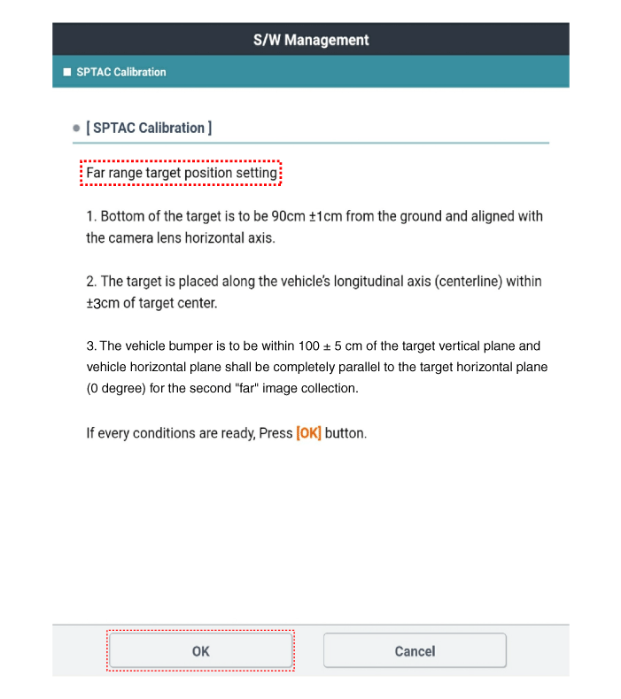
Move the calibration target (09890-3V100) 100 cm (39.37 in.) from the bumper. [Max. tolerance: ± 5 cm (± 1.97 in.)]

Set the height of the calibration target to 90 ± 1 cm (35.43 ± 0.39 in.) from the ground, and align the center of the calibration target with the center line (A) of the laser beam.
The target is positioned along the longitudinal axis (centerline) of the vehicle within ± 3 cm (± 1.18 in.) from the center of the target.
Perform long-range calibration by selecting the "OK" message on KDS after checking the position of the calibration target.

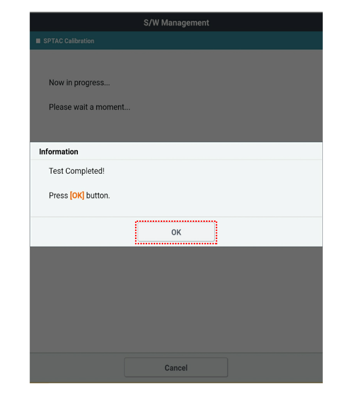
Erase the Diagnostic Trouble Codes (DTCs) using KDS.
Check the DTC and warning lamp.
Test yourself
A quick Kia Optima DL3 quiz: every answer comes with an explanation and a link to the manual page.