Engine Oil Pressure Switch Circuit
DESCRIPTION
The meter assembly and the engine oil pressure switch are connected via a dedicated line. The meter assembly determines the engine oil pressure based on the ON/OFF signal from the engine oil pressure switch.
HINT:
- The meter assembly receives various vehicle information signals from the ECM via CAN communication in order to output warnings.
- The instrument cluster assembly controls the following components to issue engine oil pressure warnings:
- Engine oil pressure warning light
- Engine oil pressure warning buzzer
- Engine oil pressure warning message on the multi-information display
WIRING DIAGRAM
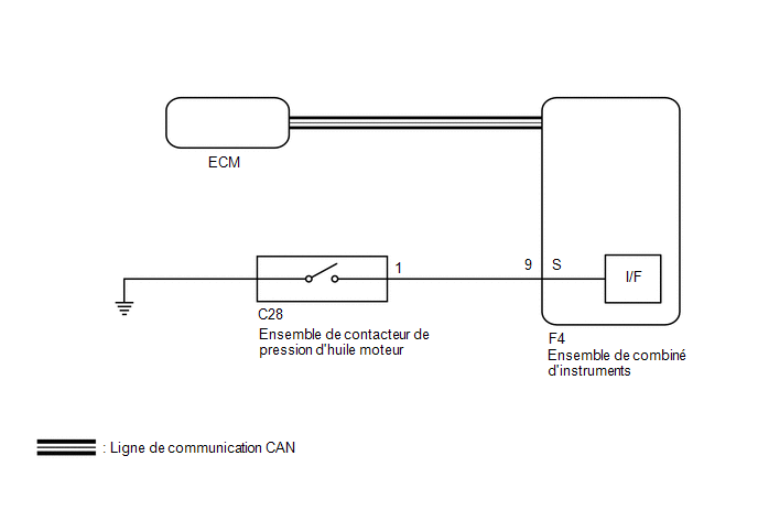
PRECAUTION / NOTICE / HINT
NOTICE:
- The following troubleshooting procedure assumes that the ECM is normal. Make sure the SFI system is not malfunctioning before performing the following procedure.
- with fuel vapor absorber pump module:
Click here

- without fuel vapor absorber pump module:
Click here
- with fuel vapor absorber pump module:
- When replacing the instrument cluster assembly, always use a new part. If an instrument cluster assembly that was installed in another vehicle is used, the stored information will not match the information transmitted by the vehicle, and a DTC may be stored.
PROCEDURE
INSPECT ENGINE OIL PRESSURE SWITCH ASSEMBLY
(a) Remove the engine oil pressure switch assembly.
Click here
(b) Inspect the engine oil pressure switch assembly.
Click here
| NG |  |
REPLACE ENGINE OIL PRESSURE SWITCH ASSEMBLY |
|

INSPECT WIRE HARNESS AND CONNECTOR (ENGINE OIL PRESSURE SWITCH ASSEMBLY - INSTRUMENT CLUSTER ASSEMBLY)
(a) Disconnect the connector from the combination meter assembly F4.
(b) Measure the resistance according to the value(s) in the table below.
Standard resistance:
Tester Connection | Condition | Specified Condition |
|---|---|---|
F4-9 (S) - C28-1 |
Always |
Below 1 Ω |
F4-9 (S) - Body ground |
Always |
10 kΩ minimum |
| OK | |
REPLACE COMBINATION METER ASSEMBLY |
| NG | |
REPAIR OR REPLACE HARNESS OR CONNECTOR |