Washer fluid level reminder switch circuit
DESCRIPTION
The meter assembly and the level warning switch assembly are connected via a dedicated line. The meter assembly determines the windshield washer fluid level and outputs warning messages based on the ON/OFF signal from the windshield washer fluid level warning switch.
WIRING DIAGRAM
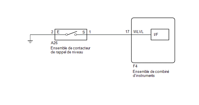
PRECAUTION / NOTICE / HINT
NOTICE:
When replacing the instrument cluster assembly, always use a new part. If an instrument cluster assembly that was installed in another vehicle is used, the stored information will not match the information transmitted by the vehicle, and a DTC may be stored.
PROCEDURE
INSPECT LEVEL WARNING SWITCH ASSEMBLY
(a) Remove the level warning switch assembly.
Click here
(b) Inspect the level warning switch assembly.
Click here
| NG |  |
REPLACE LEVEL WARNING SWITCH ASSEMBLY |
|

INSPECT WIRE HARNESS AND CONNECTOR (LEVEL WARNING SWITCH ASSEMBLY - METER ASSEMBLY AND BODY GROUND)
(a) Disconnect the connector from the combination meter assembly F4.
(b) Measure the resistance according to the value(s) in the table below.
Standard resistance:
Tester Connection | Condition | Specified Condition |
|---|---|---|
A26-1 (S) - F4-17 (WLVL) |
Always |
Below 1 Ω |
A26-1 (S) or F4-17 (WLVL) - Body ground |
Always |
10 kΩ minimum |
A26-2 (E) - Body ground |
Always |
Below 1 Ω |
| OK | |
REPLACE COMBINATION METER ASSEMBLY |
| NG | |
REPAIR OR REPLACE HARNESS OR CONNECTOR |